


Point and Arc Usage Example
Introduction
This topic explains the calculation options of the Hole Geometry SelectionManager for standard and multiaxis drilling: Point and Arc Usage (ArcUsage for multiaxis).These options determine how the software calculatesthe drilling toolpath when you select point, arc, or surface edge geometry.This information applies to both standard and multiaxis drilling, andsome other tips are provided about selecting other geometry types, whichalso apply to cross drilling.
Part 1) Ignore Z
The Ignore Z option allows you to select geometry that is above or belowthe actual hole location and have the software ignore the Z-axis valueof the geometry.This way you can set the top of feature and feature depthfor each hole group yourself.
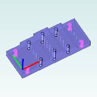
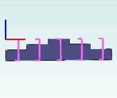
The following image shows an example drilling part and arc geometrythat is selected from above the actual hole locations.The Ignore Z optionis selected for this scenario.
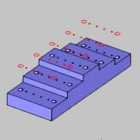
When using this option:
- The Top of Feature defaults to 0.000
- The Feature Depth defaults to
- The Diameter is automatically set from the selected arcs
- (If points are selected, the Diameter defaults to
When we navigate to the Feature page of the wizard, we see that a singlehole group is created because all of the holes share the same Diameter,Top of Feature, and Feature Depth.Note that one feature is created foreach diameter.
After selecting the group in the Hole Groups list, the preview displaysshowing these settings as described.
The next step is to break the hole group and regroup the holes.Forinformation on breaking and regrouping the holes, view the Breakand Regroup Holes Example.After breaking and regrouping the holesfor each level of the model, the Top of Feature and Feature Depth canbe set for all hole groups.
Part 2) Use as Top
The Use as Top option allows you to select geometry that is at the topof the hole and have the software calculate the toolpath using the Z-axislocation of the geometry.
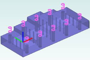
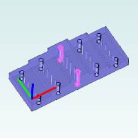
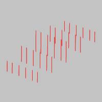
The following image shows an example drilling part and arc geometrythat is selected at the top of each hole.(Note that this could be arcsor the surface edges themselves.) The Use as Top option is selected forthis scenario.
When using this option:
- The Top of Feature is automatically set using the Z-axis locationof each arc (or surface edge)
- The Feature Depth defaults to 0.500
- The Diameter is automatically set from the selected arcs
- (If points are selected, the Diameter defaults to 1.000)
When we navigate to the Feature page of the wizard, we see that threehole groups are created: one for each Top of Feature.(Note that two featuresare created, one for each diameter.)

The next step is to set the Feature Depth for each hole group.For theexample part shown, two of the groups are broken to separate the groupsthat contains holes on opposite sides of the part.To learn more, viewthe Break and Regroup Holes Example.
Part 3) Use as Bottom
The Use as Bottom option allows you to select geometry that is at thebottom of the hole and have the software calculate the toolpath usingthe Z-axis location of the geometry.
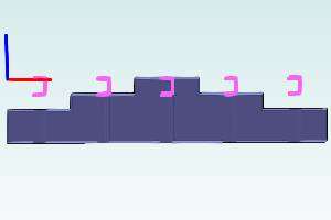
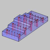
The following image shows an example drilling part and arc geometrythat is selected at the bottom of each hole.(Note that this could bearcs or the surface edges themselves.) The Use as Bottom option is selectedfor this scenario.
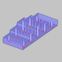
When using this option:
- The Top of Feature defaults to 0.000
- The Feature Depth is automatically set using the Z-axis locationof the selected geometry
- The Diameter is automatically set from the selected arcs
- (If points are selected, the Diameter defaults to
When we navigate to the Feature page of the wizard, we see that a singlehole group is created because all of the holes share the same Diameter,Top of Feature, and Feature Depth.(Again, one feature is created foreach diameter.)
The next step is to break the hole group and regroup the holes.Forinformation on breaking and regrouping the holes, view the Breakand Regroup Holes Example.After breaking and regrouping the holesfor each level of the model, the Top of Feature and Feature Depth canbe set for all hole groups.
Part 4) Benefits of Selecting Lines
While the Point and Arc Usage options do not apply to lines, there arestill a few important tips to note.
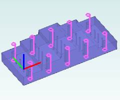
When selecting line geometry:
- The Top of Feature is automatically set to the top of the line
- The Feature Depth is automatically set to the length of the line
- The Diameter defaults to
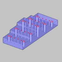
Part 5 ) Benefits of Selecting Cylindrical Surfaces
It is important to understand that selecting the cylindrical surfacesof the model directly for all holes allows the software to automaticallyset the Diameter, Top of Feature, and Feature Depth for you in the wizard.This allows the software to create hole groups using the actual dimensionsfrom the part.This may be the most efficient method to use when you havesolid or surface geometry.
When selecting cylindrical surfaces:
- The Top of Feature is automatically set using the top of the surface
- The Feature Depth is automatically set using the bottom of thesurface
- The Diameter is automatically set using the diameter of the surface
Part 6 ) Summary
This example shows that the Point and Arc Usage calculation optionsprovide you with all the options you need when selecting wireframe (point,arc, or surface edge) geometry for drilling.(Note that points cannotbe selected for multiaxis drilling, so it is just Arc Usage for that type.)
The various calculation options are provided so that you can use themost efficient method for the part you are drilling.Selecting cylindricalsurfaces is ideal when using a solid model, and the Point and Arc Usageoptions allow you to determine how the software calculates the toolpathfor wireframe geometry types.
This concludes the example.