


How to Create 2 Axis Outside Features
Introduction
In this tutorial, we examine how to create Wire EDM features while learninghow to use the Wire EDM Wizard.Most of the information provided can beapplied to either 2 Axis or 4 Axis Wire EDM features (the differencesare explained in another tutorial).A 2 Axis Outside step-by-step exampleis provided to explain many important concepts, and links are providedto help topics that further explain all parameters for each section.
This tutorial is designed to be completed first, and it should be completedwith all WireEDM Tutorials to gain a full understanding of the BobCAD-CAM WireEDM Wizard.
Example File
If you are connected to the Internet, the part file for this example can be downloaded automatically by clicking the following link: Wire EDM 2 AxisOpen Example 1.bbcd
Once you download and saved the zip file, extract the files on your system in an easy place to remember.You can then open the file to use with this tutorial.All files for the tutorials in this help system available for download can be found by clicking on the following link: http://www.bobcad.com/helpfiles.
In the example file provided,the stock and machine setup are already defined for the part.
Part 1) Add the Feature and Assign Geometry
The following is a step-by-step example of creating a 2 Axis featureand assigning geometry.
Feature and Feature Geometry
-
In the CAM Tree, right-click MachineSetup, and click 2 Axis Open.
The Wire 2 Axis Wizard displays. -
To assign the upper profile geometry, clickSelect Geometry.
The Feature Geometry Picking dialog appears and the Selected Geometry list is given focus. -
In the Layer Manager, right-click Current Profile and select Select Layer Geometry.
The entities are added to the Selected Geometry list.
Chain Direction and Start Point
-
Below the Start Point & Direction group, click in the Profile Chains list to give it focus.
The geometry highlights in the graphics area with the start point and direction shown with an arrow.
Take note of the direction in order to know which direction the path should be compensated on.
Setting a Stop Point
-
Click in the Stop Points list to give it focus.
-
Pick a point just past the middle of the intended path.
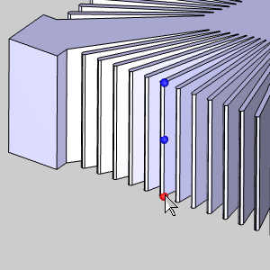
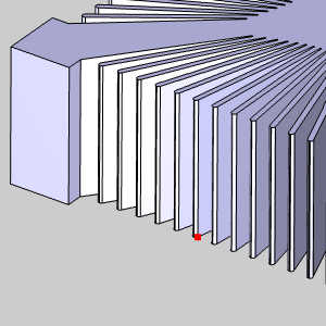
-
Click OK.
The dialog closes and the wizard returns.
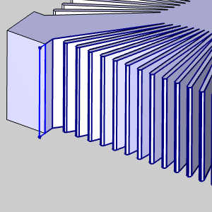
Important: You canselect geometry for 2 Axis features using solid edges (as shown), or youcan select wireframe geometry.Either way the software projects the UpperProfile to the top of the stock and projects the Lower Profile to thebottom of the stock defined for the job.The point here is that regardlessof the Z location of the selected profiles, they are always projectedto the top and bottom of the stock.
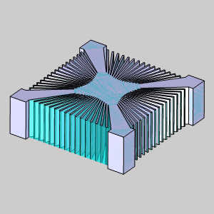
The following image shows the result of thisexample where the stock is one unit larger than the part model.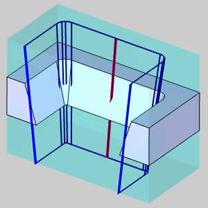
You will notice in this image the taper angle of the cut geometry no longer matches that of the model due to the projection of the geometry.
Part 2) Feature Parameters
Feature Settings
In the Feature page of the Wire EDM Wizard, the Stock Thickness displaysthe height of the stock defined for the job.(This value is for informationalpurposes and cannot be edited in the Wire EDM Wizard.)
-
Click Next>> to go to the Feature settings.
-
The Upper Guide and Lower Guidepositions are positive incremental values in reference to the topand bottom (respectively) of the stock defined for the job.For thisexample, we use the default values.
Note: Most moderncontrollers do not require the output of coordinates from the guide positions,because they are handled at the control.In most cases, these values areonly utilized for simulation purposes.
-
In the Process As group, select Punch.
-
Under Glue Stop Options, select No Glue Stop.
-
Click Next>> to go to the Machining Strategy.
Machining Strategy
-
Notice without the glue stop option selected our Current Operations include the Rough Cut, and Skim Cut, but exclude the Tab Cut as it is no longer necessary.
-
Click Next>> to go to the Wiresettings.
Wire Settings
The Wire settings of the Wire EDM Wizard contains an informational displayof the Wire Diameter for the job, options to Enable StartingCutting Conditions, and an option to set the Rapid Feedrateused for the feature.
Note: For more information, view the WireEDM Wizard Wire Settings and Howto Create Starting Cutting Conditions.
-
After making any necessary changes to theWire settings, click Next>> to go to the Posting settings.
Posting Settings
The Posting page of the Wire EDM Wizard contains Arc/Spline OutputTolerance, or the maximum amount of variation between the selectedspline, ellipse, or arc geometry and the line segments that are used toapproximate them.The tolerance can be increased or decreased as needed.The Posting Order settings only apply to 2 Axis features in whichyou assign more than one profile to the feature.To learn more, view theWireEDM Wizard Posting Settings.
-
Confirm that the proper Work Offset Numberfor the feature is selected.
-
Click Next>> to go to the MachineSequence.
Machine Sequence
-
With only one geometry chain, Machine Sequence does not effect the result.
Click Next>> to go to the Parameters.
Part 3) The 4 Axis Rough Cut
Parameters
The Standard Profile is the only pattern available.The Compensation output for Open features is definedas Off, Left, or Right for both System Compensation and MachineCompensation in the wizard.For this example, we use System CompensationLeft and MachineCompensation Off to allowthe software to compensate the wire diameter based on the offset valuesentered in the Cutting Conditions.
-
Since the direction of our chain is set to counter clockwise, we leave System Compensation to Left.
Set the Machine Compensation to Off. -
Click Next>> to go to the Corner Types page.
Corner Types
The geometry in this example does not require any change to the Corner Types, so we can skip ahead to the Leads page.
-
Click Next>> to go to the Leads page.
Leads
In the Leads page of the wizard, the Start Hole Diameter of 0.00can be left at default.All leads used in the feature will Parallel.
-
In the Lead-in group, set the Type to Parallel.
-
In the Lead-in group, update the Lengthvalue to 0.050.
-
At the bottom-left of the wizard, click Apply to All Operations.
-
Click Next>> to go to the CuttingConditions.
To learn more about leads, view the WireEDM Wizard Leads.
Cutting Conditions
The Cutting Conditions page of each operation in the Wire EDM Wizardis used to add Pass Comments, define the Cutting Conditions, and definethe Wire Speed and Tension for the operation.What is important to understandis that you have two ways to set the Cutting Conditions.You can eitherLink to Database, or you can manually enter the Cutting Conditions.Whenusing Link to Database, the Cutting Condition parameters, Offset, PowerSetting, and Feedrate, are all automatically populated from the currentlyselected database.The values that display here are determined using variousfactors from the job.The stock thickness, wire size, wire material, numberof operations, and number of passes (Skim Cut operations) all determinewhat information is available from the database.You select the CuttingConditions database for your machine in the Posting settings of the CurrentSettings dialog.
Note: Ifyou are not using the values from the Cutting Conditions database, youcan use the Edit Table option to set the Cutting Conditions forall Skim Cut passes in a single location.Remember that changing any ofthe three Cutting Conditions values (Power, Offset, or Feedrate) in theEdit Table automatically turns off Link to Database for each operationthat you edit.
-
The Cutting Conditions will be left at default for all operations in this example, so click Next>> to go to the Parametersof the Tab Cut operation.
Part 4) The Skim Cut Operation
Parameters
-
Notice all of our settings have already been set by using the Apply to All Operations button in our rough operation.
-
In the Skims group, select Reverse Skims.
The number of Skim Passes will be left to 1. -
In the Stop Settings group, clear the Apply Stop Points option.
Since the piece of stock freed from our rough operation there is no longer there, there is no reason to stop along the path. -
Click Next>> to go tothe Leads.
Leads
-
Notice all of our leads have already been set by using the Apply to All Operations button in our rough operation.
-
Click Next>> to go to the CuttingConditions.
Cutting Conditions
-
The Cutting Conditions will be left alone for now, so click Next>> to go to the Parametersof the Skim Cut operation.
-
Click Compute.
Part 6) Viewing the Wirepath
-
In the CAM Tree, right-click the feature and select Blank/Unblank Toolpath.
The wirepath is hidden. -
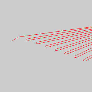
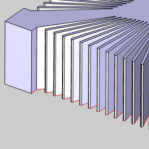
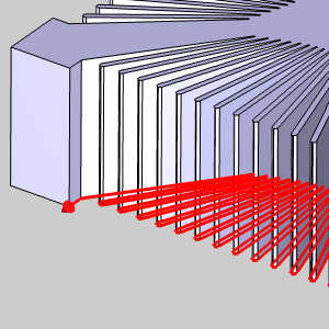
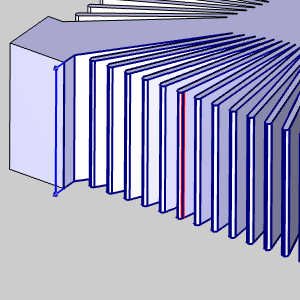
Click each operation in the feature to view the path for that specific operation.In the rough, you will notice our stop point is noted with red section.
| Rough Pass | Skim Pass |
|
|
|
Notice our rough path has the stop indication, while our skim shows the direction being reversed, and does not have a stop.This is the desired result.
This concludes the example.