How to Create 2 Axis Outside Features
Introduction
In this tutorial, we examine how to create Wire EDM features while learninghow to use the Wire EDM Wizard.Most of the information provided can beapplied to either 2 Axis or 4 Axis Wire EDM features (the differencesare explained in another tutorial).A 2 Axis Outside step-by-step exampleis provided to explain many important concepts, and links are providedto help topics that further explain all parameters for each section.
This tutorial is designed to be completed first, and it should be completedwith all WireEDM Tutorials to gain a full understanding of the BobCAD-CAM WireEDM Wizard.
Example File
If you are connected to the Internet, the part file for this example can be downloaded automatically by clicking the following link: Wire EDM 2 AxisFeatures Example 1.bbcd
Once you download and saved the zip file, extract the files on your system in an easy place to remember.You can then open the file to use with this tutorial.All files for the tutorials in this help system available for download can be found by clicking on the following link: http://www.bobcad.com/helpfiles.
In the example file provided,the stock and machine setup are already defined for the part.
The part model, stock, and machine Setup for this tutorial are shownnext.
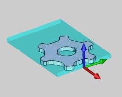
Part 1) The Feature
Feature and Feature Geometry
-
In the CAM Tree, right-click Machine Setup,and click 2 Axis Outside.
The Wire 2 Axis Wizard displays. -
In the first page of the wizard, click Select Geometryto assign the feature geometry.
The Feature Geometry Picking dialog appears with focus on the Selected Geometry list by default. -
In the graphics area, select a closed outsideprofile to cut.This can be wireframe geometry or the edges of a solid.The following images show both selection types for the same feature.
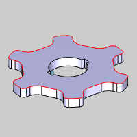
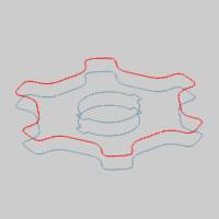
The geometry is added to the Selected Geometry list.
Tip: For 2Axis features, you select a single profile from the top or bottom of thepart.The software automatically projects the selected profile to thebottom (and top) of the stock defined for the job (2 Axis features withouttaper).When applying taper to a 2 Axis feature, select the profile fromany Z-height and use the Taper from Bottom option to apply the taper tothe bottom or top of the feature.
-
After selecting the profile, click in the Profile Chains list to give it focus.
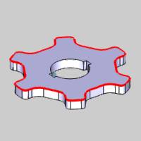
Notice the location of the Start Point.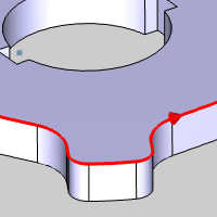
While your start point may appear in a different location based on where you selected geometry, what is important to note here is we could select our feature start point at this time by choosing one of the options in the Start Point & Direction group.This can also be done by simply clicking in the graphics area to update the start point location and direction.For the purposes of this example we leave the start point as it is to update after the feature is computed. -
For this example no stop points are used, so click
 OK to confirm and return to the wizard.
To learn more about selecting geometry, view the WireEDM Wizard Geometry Selection. -
Click Next>> to go to the Feature settings.
Feature Settings
In the Feature page of the Wire EDM Wizard, the Stock Thickness displaysthe height of the stock defined for the job.(This value is for informationalpurposes and cannot be edited in the Wire EDM Wizard.)
-
The Upper Guide and Lower Guidepositions are positive incremental values in reference to the topand bottom (respectively) of the stock defined for the job.For thisexample, we use the default values.
Note: Most moderncontrollers do not require the output of coordinates from the guide positions,because they are handled at the control.In most cases, these values areonly utilized for simulation purposes.
-
Under Glue Stop Options, confirm that Use Glue Stop withLeads is selected.
When Use Glue Stop is selected, the first operation in the featuredoes not cut the entire profile.Instead it leaves a glue stop, definedby the Stop Distance, at the end of the chain.The glue stop is thencut using a separate Tab Cut operation.If you select No Glue Stop,then all feature operations cut the entire profile.
The default Stop Distance, 0.100, is used for this feature. -
The walls of our part are not tapered, so the Taper Settingis set to None.
-
Click Next>> to go to the Machining Strategy.
Machining Strategy
-
In the Machining Strategy, the Default Strategy of 2 Axis Outside Strategy1 is used.
This adds a Rough Cut, Skim Cut, and Tab Cut operation to the CurrentOperations list.Notice that because this is an outside feature, theSkim Cut operation is before the Tab Cut operation.If we performedthe Tab Cut operation before the Skim Cut, our part would no longerbe held in place. -
Click Next>> to go to the Wiresettings.
Wire Settings
The Wire settings of the Wire EDM Wizard contains an informational displayof the Wire Diameter for the job, options to Enable StartingCutting Conditions, and an option to set the Rapid Feedrateused for the feature.
Note: For more information, view the WireEDM Wizard Wire Settings and Howto Create Starting Cutting Conditions.
-
After making any necessary changes to theWire settings, click Next>> to go to the Posting settings.
Posting Settings
The Posting page of the Wire EDM Wizard contains Arc/Spline OutputTolerance, or the maximum amount of variation between the selectedspline, ellipse, or arc geometry and the line segments that are used toapproximate them.The tolerance can be increased or decreased as needed.The Posting Order settings only apply to 2 Axis features in whichyou assign more than one profile to the feature.To learn more, view theWireEDM Wizard Posting Settings.
-
Confirm that the proper Work Offset Numberfor the feature is selected.
-
Click Next>> to go to the MachineSequence.
Machine Sequence
The Machine Sequence is only used to determine the cut order when morethan one profile is assigned to a 2 Axis feature and can be ignored since we only have one chain selected.For more information,view the WireEDM Wizard Machine Sequence.
-
Click Next>> to go to the Parametersof the first operation, which is our Rough Cut.
Part 2) The Rough Cut Operation
Parameters
The Standard Profile is the only pattern available for Outsidefeatures.The Compensation output for Outside features is definedas On or Off for both System Compensation and MachineCompensation in the wizard.The software automatically outputs thecorrect compensation codes based on your selections and the chain directionof the feature.For this example, we use System CompensationOn and MachineCompensation Off to allowthe software to compensate the wire diameter based on the offset valuesentered in the Cutting Conditions.
-
Set the System Compensation to On.
-
Set the Machine Compensation to Off.
-
In this example stop points are not used, so click Next>> to go to the CornerTypes.
Corner Types
The Corner Types allow you to define the type of corner output for bothExternal Corners and Internal Corners separately for the operation.
Note: To learnmore, view the WireEDM Wizard Corner Types.
-
For this example, both External Cornersand Internal Corners are set to Sharp.
-
Click Next>> to go to the Leads.
Leads
In the Leads page of the wizard, the Start Hole Diameter of 0.00is used because we are leading into the profile of the part from outsidethe stock.The Thread Vertical option is selected to force theupper and lower guides to align vertically at the start of the lead-into the feature (the threading location).(For 2 Axis features with notaper, this option does not change the wirepath.)
For both the Lead-in and Lead-out of the feature, we usethe default Type, Perpendicular.Because we are leading into theprofile from outside the stock, we use the Perpendicular lead moves from the Start Point we selected during geometry selection.We also want to make our RoughCut lead-in longer in order to begin outside the stock.We then only needa small lead-out move for the next operation.
-
In the Lead-in group, update the Lengthvalue to 0.300.
This makes our lead-in start from just outside the stock. -
In the Lead-out group, click to clear theSame as Lead-in check box.
-
Update the Length value to 0.050.
-
Click Next>> to go to the CuttingConditions.
To learn more about leads, view the WireEDM Wizard Leads.
Cutting Conditions
The Cutting Conditions page of each operation in the Wire EDM Wizardis used to add Pass Comments, define the Cutting Conditions, and definethe Wire Speed and Tension for the operation.What is important to understandis that you have two ways to set the Cutting Conditions.You can eitherLink to Database, or you can manually enter the Cutting Conditions.Whenusing Link to Database, the Cutting Condition parameters, Offset, PowerSetting, and Feedrate, are all automatically populated from the currentlyselected database.The values that display here are determined using variousfactors from the job.The stock thickness, wire size, wire material, numberof operations, and number of passes (Skim Cut operations) all determinewhat information is available from the database.You select the CuttingConditions database for your machine in the Posting settings of the CurrentSettings dialog.
Note: TheEdit Table button is provided as a convenient way to set the CuttingConditions for all operations (and passes) contained in a feature froma single location.This method should only be used when you want to manuallyenter the Cutting Conditions.When you change any of the three CuttingConditions values in the Edit Table, Link to Database is automaticallyturned off for that operation.Changing the Pass Comment, Tension, or Speed in the main Cutting Conditions page of the wizard does not turn off Link to Database.Stepsare provided later in this example to show how this works.
-
At the top of General Settings group of the Cutting Conditions page, notice Link to Database is selected.
In the Cutting Conditions group, notice all three Cutting Conditions values are unavailable. -
Click to clear the Link to Database checkbox.
Notice the three Cutting Conditions parameters are now available forediting. -
Click to select the Link to Database checkbox since we are using the database values for this example.
Notice in the Wire Speed and Tension group the Speed and Tension values are still available.Only the three Cutting Conditions parameters are linked to thedatabase. -
Click Next>> to go to the Parametersof the Skim Cut operation.
Part 3) The Skim Cut Operation
Parameters
The Standard Profile is the only Pattern available forSkim Cut operations.
-
In the Skims group, select Reverse Skims.
This means that the direction of each Skim Cuts pass will alternate direction.
Furthermore, this means the first Skim Cut pass cuts in the oppositedirection of the previous operation. -
In the Number of Skim Passes field,set the value to 2.
This setting means that the Skim Cut operation consists of two passes,which allows for more accurate cutting and better finishing of thepart. -
Set System Compensation to On.
-
Set MachineCompensation to Off.
-
Click Next>> twice to go tothe Leads.The default Corner Type, Sharp is used forExternal and Internal Corners, so the Corner Types page is skipped.
Leads
-
In the Lead-in group, set the Lengthvalue to 0.050.
This makes the lead-in move of the Skim Cut operation the same as thelead-out of the Rough Cut operation.Also, because the Same as Lead-incheck box is selected in the Lead-out group, the lead-out uses thesame settings. -
Click Next>> to go to the CuttingConditions.
Cutting Conditions
Important: The Cutting Conditions of the Skim Cut operation are handled the sameas explained in the Rough Cut operation section of this topic, with onemajor difference.The Selected Pass option is important when setting theCutting Conditions for Skim Cut operations.Skim Cut operations can containone or more passes, and the values that display in this page only applyto the currently Selected Pass.You must select each pass in the SelectedPass list in order to set the Cutting Condition for all passes containedin the operation.
Note: Ifyou are not using the values from the Cutting Conditions database, youcan use the Edit Table option to set the Cutting Conditions forall Skim Cut passes in a single location.Remember that changing any ofthe three Cutting Conditions values (Power, Offset, or Feedrate) in theEdit Table automatically turns off Link to Database for each operationthat you edit.
The following stepsare included to help you understand how to use the Edit Table.
-
With 2 Axis Skim Cut: Pass #1 selectedin the Selected Pass list, click Edit Table.
-
Next to 2 Axis Skim Cut: Pass #1, click in the Power Settingfield and update the value to 782.
-
At the bottom of the dialog, click OK.
Notice that the Link to Database check box is no longer selected.Becausewe edited a Cutting Conditions parameter (Offset, Power Setting, andFeedrate), the software automatically unlinks the operation from thedatabase.
-
-
Click to select the Link to Databasecheck box.
Notice that the values in the Cutting Conditions group are changed back to the databasevalues. -
Click Edit Table.
-
Next to 2 Axis Skim Cut: Pass #2,click in the Speed field and update the value to10.
-
Press Tab, and in the Tension field type 10.
-
Press Tab again (so the focus is inthe Comments column), and type Comment Testing.
-
Click OK to close the Cutting Conditions dialog.
-
Warning: Thevalues provided (Power, Speed, Tension) in this example for the purposeof showing how to use the Cutting Conditions may or may not be appropriatevalues.You must confirm all Cutting Conditions are correct before runninga program on your machine.
Notice that none of the values you just enteredin the Edit Table display in the wizard.This is because the SelectedPass is still Skim Pass #1.
-
Under Selected Pass, click the down arrow and select2 Axis Skim Cut: Pass #2.
The Wire Speed and Tension and the Pass Commentnow display as entered in the Edit Table earlier.
Notice that the software didn’t unlink theoperation from the database.This is because none of the Cutting Conditions parameters(Offset, Power Setting, or Feedrate) were changed.The Wire Speed andTension and the Pass Comment are not tied to the database.
Note: The WireSpeed and Tension are not used for all machine types.These values canbe set to zero if they are not needed.
-
Click Next>> to go to the Tab Cut operation Parameters.
Part 4) The Tab Cut Operation
Parameters
The Standard Profile is the only Pattern used for TabCut operations.Notice the Use Knockout parameter in the Patternsgroup.This parameter allows you specify a Knockout Distance, which isthe length of the Glue Stop which is not cut by the Tab Cut operation.For our example we want to cut the entire Glue Stop with the Tab Cut operation,so no change is needed.
-
In the Compensation group, set SystemCompensation to On.
-
Set the Machine Compensationto Off.
-
Click Next>> to go to the Leads.
Leads
-
In the Lead-in group, update the Lengthto 0.050.
-
Click Next>> to go to the CuttingConditions.
Cutting Conditions
-
Set the Cutting Conditions for the Tab Cut operation using either Linkto Database, or manually enter the values after clearing the Link to Databasecheck box.
Compute
-
At the bottom of the dialog box, click Computeto create the wirepath for the feature.
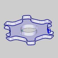
Tip: To makethe wirepath easier to view, the part is made transparent (press T orclick View, Transparent), and the Rough Cut operation is selected in theCAM Tree to highlight the operation.
Part 2) Updating the Feature Start Point
After finishing the wizard, the featureis added to the CAM Tree below the Machine Setup.The feature in the CAM Tree contains the Geometry item, which is usedto modify the Start Point in addition to selecting or modifying geometry, and selecting Stop Points.Setting the Start Point is an important part of properly setting up yourWire EDM features.The following steps explain how to set the Start Point.
Note: For more information, see the WireEDM Features Overview topic.
-
In the CAMTree under
 FeatureEDM 2X Outside, right-click
  Geometry,and click Modify Start Point.
The Feature Geometry Picking dialog appears.
This is the same dialog which would open by selecting Re/Select instead of Modify Start Point.However, you will notice it is the Profile Chains list which has focus instead of the Selected Geometry list. -
In the graphics area, click the desired startpoint location on the feature geometry.
Tip: You don’t actually have to click the geometrydirectly to move the start point, Modify Start Point uses the screen positionof the mouse pointer, but depending on the current view, it is often easiestto click the geometry directly.
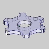
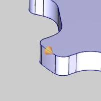
-
To confirm the new start point location,click
 (OK).
(OK).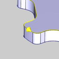
-
After modifying the start point of the feature, you must computethe wirepath to update the change.
In the CAM Tree, right-click Feature 2X EDM Outside, and click ComputeAll Toolpath.
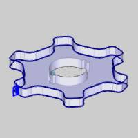
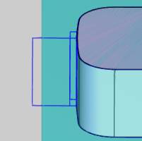
The wirepath updates to the new start point.Notice how the first operation's lead in move is from outside the stockand all other lead moves are much shorter as explained previously.
This concludes the example.


