


How to Create a 4 Axis Inside Wire Feature
Introduction
Example File
If you are connected to the Internet, the part file for this example can be downloaded automatically by clicking the following link: Wire EDM 4 Axis
Inside Example 1.bbcd
Once you download and saved the zip file, extract the files on your system in an easy place to remember. You can then open the file to use with this tutorial. All files for the tutorials in this help system available for download can be found by clicking on the following link: http://www.bobcad.com/helpfiles.
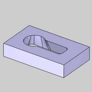
In the example file provided, the stock and machine setup are already defined for the part.
Part 1) Add the Feature and Assign Geometry
One main difference between 2 Axis and 4 Axis Wire EDM features is the geometry selection. While 2 Axis features only require a single profile, 4 Axis features require an Upper Profile and Lower Profile. In addition to the two profiles, you can also select Sync Line geometry to determine the alignment of the wire between the upper and lower profiles.
The following is a step-by-step example of creating a 4 Axis feature and assigning geometry.
Feature and Feature Geometry
-
In the CAM Tree, right-click Machine Setup, and click 4 Axis Inside.
The Wire 4 Axis Wizard displays. -
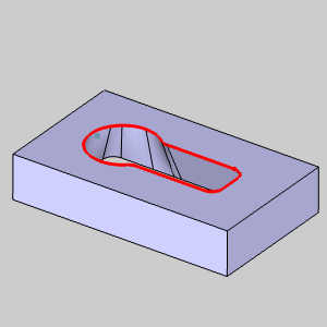
To assign the upper profile geometry, click Select Upper Profile.
The Feature Geometry Picking dialog appears and the Upper Geometry list is given focus. -
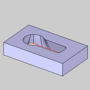
In the graphics area, right-click the inner surface edge at the top of the model, and click Constant Z.
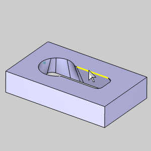
The entities are added to the Upper Geometry list. -
Click in the Lower Geometry list to give it focus.
-
Right-click the lower surface edge, and click Constant Z.
The entities are added to the Lower Geometry list.
Chain Direction and Start Point
-
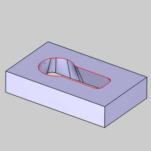
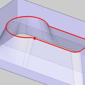
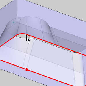
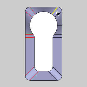
Below the Start Point & Direction group, click in the Upper Profile Chain list to give it focus.
The geometry highlights in the graphics area with the start point and direction shown with an arrow. -
Zoom in and notice the current location.
-
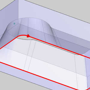
Click in the Lower Profile Chain list to and view the start point and direction.
While your location may differ based on how the geometry was selected it is important to notice each chain has the same direction and, in the images used here, are positioned on the same surface edge. This is critical to produce good wirepath. The locations in the above images would work if our start hole was closer, but we will be using the point shown in the images and so these should be updated. The locations of the start point can be updated by clicking in the graphics area near the entity you want to start on. -
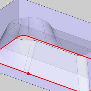
Move your mouse to the bottom of a surface edge, click once, and leave your mouse in that location.

The Start Point moves to that location. -
Click again in the same location.
The chain direction reverses. -
Next to the Lower Profile Chain list, click the reverse button to correct the direction.
Using Closest to Points
-
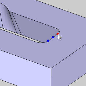
While we could update the Start Point location this way, in the Start Point group, select the check box for Closest to Points.
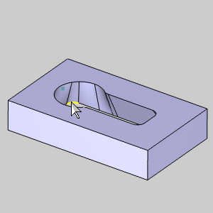
The Selected Points list becomes available. -
Click in the Selected Points list to give it focus and select the point.

The point is added to the list. -
Click the Closest to Points button.
-
Now, click in Upper Profile Chain and Lower Profile Chain lists once more to note the location of our Start Point.
Setting a Stop Point
-
For this example we do not select any Sync Line geometry, but we do want to create a stop on the other end of our selected chains.
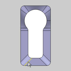
Click in the Stop Points list to give it focus. -
Click on the end of the surface edge shown to select a point.
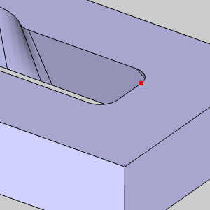
The point is added to the list. -
Click OK to confirm geometry selection.
The dialog closes, and the Wire 4 Axis Wizard opens.
Important: You can
select geometry for 4 Axis features using solid edges (as shown), or you
can select wireframe geometry. Either way the software projects the Upper
Profile to the top of the stock and projects the Lower Profile to the
bottom of the stock defined for the job. The point here is that regardless
of the Z location of the selected profiles, they are always projected
to the top and bottom of the stock.
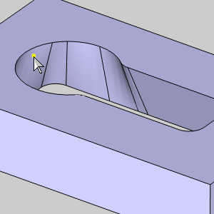
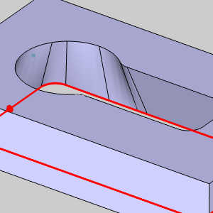
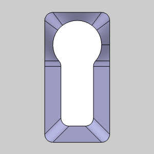
The following image shows the result of this
example where the stock is one unit larger than the part model.
You will notice in this image the taper angle of the cut geometry no longer matches that of the model due to the projection of the geometry.
Part 2) Feature Parameters
Feature Settings
In the Feature page of the Wire EDM Wizard, the Stock Thickness displays the height of the stock defined for the job. (This value is for informational purposes and cannot be edited in the Wire EDM Wizard.)
-
Click Next>> to go to the Feature settings.
-
The Upper Guide and Lower Guide positions are positive incremental values in reference to the top and bottom (respectively) of the stock defined for the job. For this example, we use the default values.
Note: Most modern controllers do not require the output of coordinates from the guide positions, because they are handled at the control. In most cases, these values are only utilized for simulation purposes.
-
Under Glue Stop Options, confirm that Use Glue Stop with Leads is selected.
When Use Glue Stop is selected, the first operation in the feature does not cut the entire profile. Instead it leaves a glue stop, defined by the Stop Distance, at the end of the chain. The glue stop is then cut using a separate Tab Cut operation. If you select No Glue Stop, then all feature operations cut the entire profile. -
The default Stop Distance, 0.100, is used for this feature.
-
Click Next>> to go to the Machining Strategy.
Machining Strategy
-
In the Machining Strategy, the Default Strategy of 4 Axis Inside Strategy 1 is used.
This adds a Rough Cut, Tab Cut, and Skim Cut operation to the Current Operations list. -
Click Next>> to go to the Wire settings.
Wire Settings
The Wire settings of the Wire EDM Wizard contains an informational display of the Wire Diameter for the job, options to Enable Starting Cutting Conditions, and an option to set the Rapid Feedrate used for the feature.
Note: For more information, view the Wire EDM Wizard Wire Settings and How to Create Starting Cutting Conditions.
-
After making any necessary changes to the Wire settings, click Next>> to go to the Posting settings.
Posting Settings
The Posting page of the Wire EDM Wizard contains Arc/Spline Output Tolerance, or the maximum amount of variation between the selected spline, ellipse, or arc geometry and the line segments that are used to approximate them. The tolerance can be increased or decreased as needed. The Posting Order settings only apply to 2 Axis features in which you assign more than one profile to the feature. To learn more, view the Wire EDM Wizard Posting Settings.
-
Confirm that the proper Work Offset Number for the feature is selected.
-
Click Next>> to go to the Parameters.
Part 3) The 4 Axis Rough Cut
Parameters
The Standard Profile is the only pattern available. The Compensation output for Inside features is defined as On or Off for both System Compensation and Machine Compensation in the wizard. The software automatically outputs the correct compensation codes based on your selections and the chain direction of the feature. For this example, we use System Compensation On and Machine Compensation Off to allow the software to compensate the wire diameter based on the offset values entered in the Cutting Conditions.
-
Set the System Compensation to On.
-
Set the Machine Compensation to Off.
-
At the bottom-left of the wizard, click Apply to All Operations.
-
Click Next>> to go to the Leads page.
Leads
In the Leads page of the wizard, the Start Hole Diameter of 0.00 can be left at default. The Thread Vertical option is cleared to reduce wire movement in the other operations.
Besides the first Lead-in, all leads used in the feature will be the default Type, Perpendicular.
-
In the Lead-in group, update the Length value to 0.050.
-
At the bottom-left of the wizard, click Apply to All Operations.
With all the other leads now set, we only need to update our Lead-in. -
In the Lead-out group, clear the check box for Same As Lead-in.
-
In the Lead-in group, update the Length value to 0.275.
-
Click Next>> to go to the Cutting Conditions.
To learn more about leads, view the Wire EDM Wizard Leads.
Cutting Conditions
-
The Cutting Conditions will be left at default for all operations in this example, so click Next>> to go to the Parameters of the Tab Cut operation.
Part 4) The Skim Cut Operation
Parameters
-
In the Skims group, select Reverse Skims.
-
Set the Number of Skim Passes to 2.
-
Our other settings have already been applied.
-
Click Next>> to go to the Leads.
Leads
-
Notice all of our leads have already been set by using the Apply to All Operations button in our rough operation.
-
Click Next>> to go to the Cutting Conditions.
Cutting Conditions
-
The Cutting Conditions will be left alone for now, so click Next>> to go to the Parameters of the Skim Cut operation.
Part 5) The Tab Cut Operation
Parameters
-
Notice all of our settings have already been set by using the Apply to All Operations button in our rough operation.
-
Click Next>> to go to the Leads.
Leads
-
Click Next>> to go to the Cutting Conditions.
Cutting Conditions
-
Default cutting conditions are used, so click Compute to view the wirepath.
Part 6) Viewing the Wirepath
-
In the CAM Tree, right-click the feature and select Blank/Unblank Toolpath.
The wirepath is hidden. -
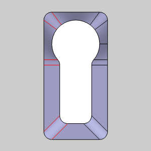
Click each operation in the feature to view the path for that specific operation. In the rough, you will notice our stop point is noted with red section.
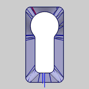
-
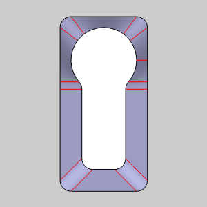
From a top view, notice the path does not quite align with our surface edges. This is most evident in the radii at the bottom of the image.
| Path alignment | Surface edges |
|
|
|
Part 7) Adding Sync Lines
-
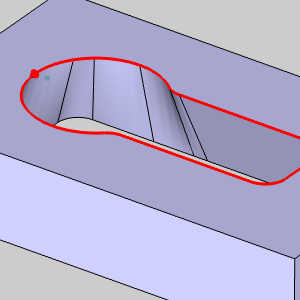
In the feature in the CAM Tree, right-click Sync Lines and select Re/Select.
The Feature Geometry Picking dialog opens with focus on the Sync Lines list. -
Begin selecting the surface edges on the left side of the part.
-
Click OK.
-
Right-click the feature and select Compute All Toolpath.
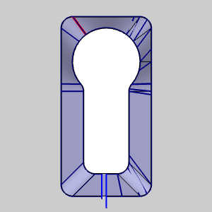
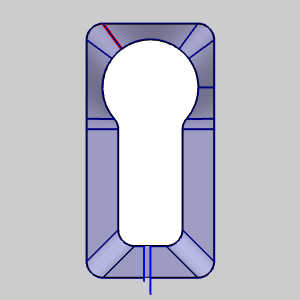
| Path alignment | Surface edges |
|
|
Notice at each of the selected sync lines the wire is aligned.
-
In the feature in the CAM Tree, right-click Sync Lines and select Re/Select.
The Feature Geometry Picking dialog opens with focus on the Sync Lines list. -
Select the remaining surface edges on the right side of the part.
-
Click OK.
-
Right-click the feature and select Compute All Toolpath.
The path is now synced with the geometry.
This completes the tutorial.