


The Selections
Introduction
This topic will explain what Selections are, what the Selections manager is, where to find it, and explain the functionality of Selections and the Selections Manager.
Selections
The Selections are groups of one or more entities which have been selected and saved, as a single selectable item, for easy future selection. How Selections are utilized is completely up to the user, however, the general idea is that if there is a group of entities that takes a moment to select and will need to be selected again later, that group can be saved in order to select, or deselect it in the future with a single click.
The Selections Manager
The Selections Manager is located, by default, on the right side of the application, above the UCS Manager, and to the left of the Layers Manager. The location of the Selections Manager, however, can be adjusted to preference, as explained in the Introduction to Docking Panes topic. The purpose of the Selections Manager is to provide a way to keep your required selections organized, and easy to select.![]()
The Selections Manager Quick access menu
-
 Save current selection - saves the selected geometry as a selection in the selections manager.
 -
 Delete selection - removes the highlighted selection from the selections manager.
The Selections
As soon as a selection is saved it is added to the Saved Selection folder.The folder, and each saved selection can be collapsed and expanded as needed.
![]()
![]() Saved Selection
Saved Selection
![]()
![]() Selection 1 (3)
Selection 1 (3)
![]()
![]() Solid/Surface-109
Solid/Surface-109
![]()
![]() Line-222
Line-222
![]()
![]() Line-223
Line-223
![]()
![]() Selection 2 (1)
Selection 2 (1)
![]() Arc-19
Arc-19
Warning: Translating/Rotating, or otherwise altering the geometry contained in the saved selections breaks the association. An ![]() icon will appear next to items that have had their associations broken. And the selections will need to be updated manually.
icon will appear next to items that have had their associations broken. And the selections will need to be updated manually.
The Saved Selection folder and Selections
-
 Saved Selection - The Saved Selection folder houses all selections and can be collapsed and expanded as needed.Right-click the Saved Selection folder to:
 -
Delete All - removes all selections from the Selections Manager.
-
-
 Selection _ (_) - Selections are added to the Saved Selection folder as they are created.Each will note the number of entities in the selection with parentheses.Right-click the selections to:
 -
Re/Select - opens the Selections dialog in order to let you add or remove geometry to the saved selection.
-
OK - saves entities currently in the Selected Geometry list to the selection and closes the dialog.
-
Cancel - discards the changes and closes the dialog.
-
-
Delete - removes the selection from the Saved Selection folder.
-
Rename - allows you to alter the name of the selected item.The parentheses, and the entity count inside those parentheses is saved to the update.
-
Quick Steps - Selections
-
Enter selection mode.
-
Select the desired geometry in the graphics area.
-
In the Selections Manager, click
 Save current selection.
The selection is saved in the Selections Manager as Selection 1 (*number of entities*). -
Click the saved selection to deselect the geometry in the graphics area.
-
Right-click the selection and select Rename.
-
Set the name and press Enter.
Notice the name updates and the number of entities in parentheses remains. -
Right-click the save selection and select Re/Select to update the geometry saved for the selection as needed.
Example - Selections
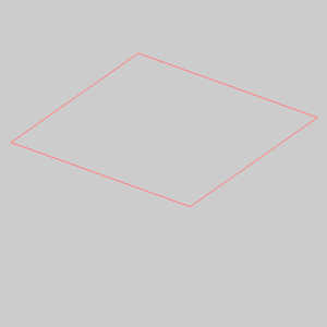
Step 1) Creating Entities
-
In the Shapes group, of the Create 2D ribbon, click
 Rectangle.
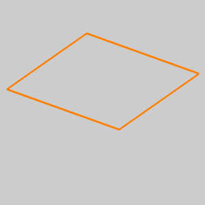
The preview of a 2*2 square appears. -
Click OK.
The entities are created and a preview of the current rectangular parameters are still shown. -
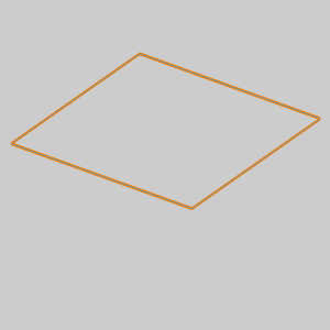
Update the Length and Width of the Rectangle to 1.750.
The preview updates. -
Click OK.
-
Repeat this process to create another two rectangles with a length and width of:
-
1.500.
-
1.250.
-
-
Click Cancel.

Step 2) Creating saved Selections
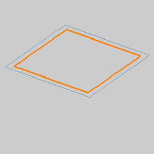
-
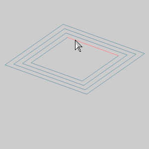
Enter selection mode, hover over one of the entities of the inner rectangle, hold Shift and Left-click to chain select all the entities.
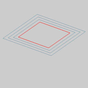
-
In the Selections Manager, click
Save current selection.
The selection is saved in the Selections Manager as Selection 1 (4). -
In the Selections Manager, click
Selection 1 (4) to deselect the entities. -
Repeat these steps to create a saved section for each rectangle starting with the next smallest and ending with the largest.
-
In the Selections Manager, select Selection 2 and Selection 3.
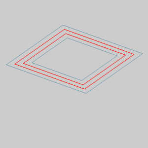
-
Click
Save current selection.
The selection is saved in the Selections Manager as Selection 5 (8). -
Right-click Selection 5 and select Rename.
The full name, Selection 5 (8), is highlighted for updating. -
Update the name to Channel and press Enter.
Notice the entity count is automatically added to the end of the name. -
Click Channel to deselect the geometry.
-
In the Layers Manager, click
 New Layer to add another layer.
Layer-1 is added to the Layers list and is automatically set as the active layer. -
Click
 next to the CAD layer to hide that layer.
The geometry is hidden.
Step 3) Using Selections
- In the Extrude group, of the Create 3D ribbon, click
 Extrude Boss.
The Extrude Boss dialog opens in the Data Entry Manager. - In the Selections Manager, hover over Section 1.

Notice the entities highlight even when they are hidden. - Click Selection 4 to add it to the Selected Geometry list.
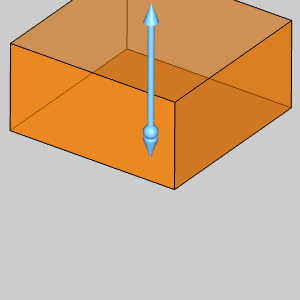
Notice each of the saved entities is added to the list, and the preview appears. - In the Positive Direction group, set the Distance to 0.000 and press Tab.
The Distance is the Other Direction group is automatically set to 1.000.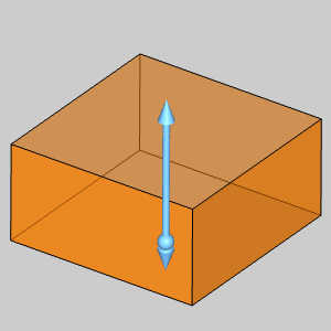
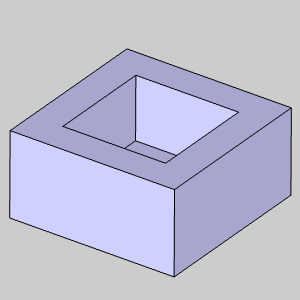
- Click OK.
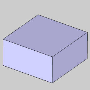
The boss is created. - In the Extrude group, of the Create 3D tab, click
 Extrude Cut.
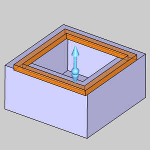
The dialog updates. - Click Selection 1 to add it to the Selected Geometry list.
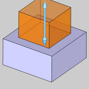
Notice each of the saved entities is added to the list, and the preview appears. - In the Positive Direction group, set the Distance to 0.000 and press Tab.
The Distance is the Other Direction group is automatically set to 1.000. - Update the Other Direction Distance to 0.750.
- Click OK.
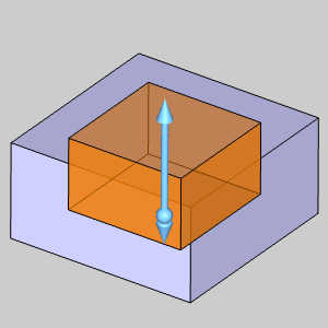
The Extrude Cut is created. - Update the Other Direction Distance to 0.125.
- In the Selections Manager, select Channel (8).
The preview appears. - Click OK.
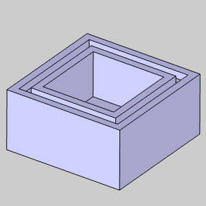
The Extrude Cut is created for the channel. - Click Cancel.
This concludes the example.