


How to Create a 4 Axis Wrapping Feature
Introduction
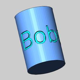
To create 4-axis wrapped features, you use the Wrapping Group in the CAM Tree. In this tutorial you create a 2-axis feature in a Wrapping Group to cut text around a cylindrical part. The part is a 6-inch cylinder that is created by the stock (no part model is used), and the feature geometry is text, which is created in the first part of this tutorial.
This topic is supplemental to the Wrapping Group.
Example

CAD: Part 1) Draw the Part Boundary
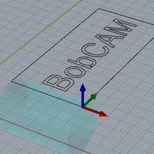
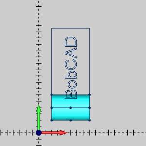
The following steps create a rectangle as a reference to the boundary of the unwrapped surface of the cylinder. This is only used as a visual aid and is not required for the part. The zero degree location of the boundary is placed at the zero degree location of the part/stock.
- In the Quick Access Toolbar, click
 New.
New. - In the Shapes group, of the Create 2D ribbon,
click
 Rectangle, and
type the following values in the
Data Entry Manager.
Rectangle, and
type the following values in the
Data Entry Manager.
Length (X) = 6.000
Width (Y) = 12.566
Tip: The Width (Y) value is the circumference of the cylinder. This was found by using the formula: C = PI * diameter.
- Under Origin, click
the down arrow, and select Bottom
Left.
Type the following values:
X = 2.000
Y = 4.000
Z = 0.000 - To create the rectangle, click OK.
- Click Cancel to close
the Data Entry Manager.
Click anywhere in the graphics area, and press the F key to activate the View, Fit All command.
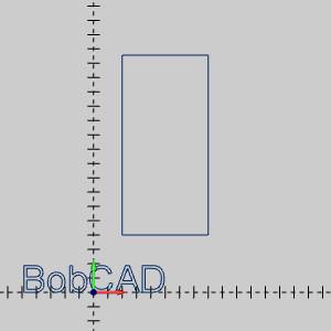
CAD: Part 2) Create the Feature Geometry
- In the Text group, of the Create 2D ribbon, click
 Text. (This may
take a few moments to load all of the fonts for the function.)
Text. (This may
take a few moments to load all of the fonts for the function.) - Click BobCAD
Font, click the font arrow, and at the bottom of the list,
select Stamp.
- Below the font list, click in the white box
and type BobCAD.
- In the Height
box, type 2.000.
- Click Drag.
- To create the text, click OK.
- Click Cancel.
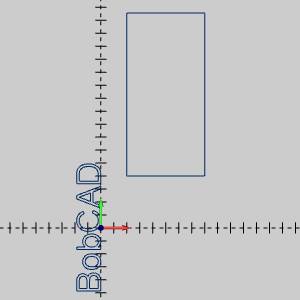
CAD: Part 3) Rotate the Geometry
- In the Move group of the Utilities ribbon,
click
 Rotate.
The parameters display in the Data Entry Manager. - Under Angle
Around Axis, in the Z
box, type 90.00.
- In the Origin group, confirm the X,
Y, and Z
values are all 0.000.
- In the graphics
area, click to select the geometry (text).
To confirm the selection, press the Spacebar. - To rotate the text, click
OK.
- Click Cancel.
Note: The Text function also contains an Angle parameter that allows you to rotate the text in the graphics area. We didn't use this parameter so that we could instead show you how to use the Rotate function to rotate existing geometry.
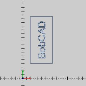
CAD: Part 4) Move the Geometry Using Translate
- In the Move group, of the Utilities ribbon,
click
 Translate.
- In the End
group, type the following values:
X = 6.000
Y = 10.283
Z = 0.000 - The CAD preview displays the text in the center of the rectangle.
- To move the geometry as shown in the CAD preview, click OK.
- Click Cancel to close
the Data Entry Manager.
The part geometry needed for the job is finished. The next step is to create the Milling Job.
CAM: Part 1) Create a Milling Job
- Click the CAM
Tree tab.
- Right-click CAM
Defaults, and click New Job.
By default the Milling Job Type is selected. - In the Machine
group, select BC_4x_Mill from the drop down list.
- To define the stock geometry, click Stock Wizard.
CAM: Part 2) Create the Stock
- In the Data
Entry tab, click
 to skip the workpiece assignment.
The default Rectangular stock appears on the geometry. - Select
 Cylindrical.
 - In the Stock
Orientation group, click the Extrusion
Direction arrow, and select X
Axis.
- In the Dimension / Offset
group, type the following values:
Diameter = 4.0
Height = 6.0
The stock size updates. - In the Stock Orientation
group, click Enter Origin.
Type the following values:
X = 8.0
Y = 4.0
Z = -2.0
The stock location updates. - Click to go to the Machine Setup.
Wireframe appears on the stock allowing you to select common locations to set as the Machine Setup location.
CAM: Part 3) Define the Machine Setup
- In the Origin
group, click the Origin button.
- In the graphics area, click near the right
side of the line on top of the stock, as shown next. (Be sure that
the line is highlighted when you click.)
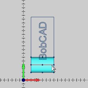
This defines the machining origin (work offset) location on the stock. - In the Work Offset XYZ group of the Work Offset section, set the X,Y, and Z values to:
X = 0.0
Y = 0.0
Z = 2.0
Note: This setting defines the distance from the virtual machine zero (center face of rotary table) to the machining origin. In this example, because the machining origin is not the same as the machine zero, the difference is reported in the Work Offset dialog box. This is required to create proper machine simulation and posting. (If the machining origin is placed at the center of rotation, then the work offset values are all 0.00.)
- Use the default Clearance Plane
value of 1.000, and click OK to finish the Machine Setup.
The stock, and Machine Setup are set.
CAM: Part 4) Add the Wrapping Group to the Machine Setup
- In the CAM Tree, right-click
 Machine Setup,
point to Additional Functions,
and click Add Wrapping Group.
Machine Setup,
point to Additional Functions,
and click Add Wrapping Group.
The Wrapping Group dialog box displays. -
Click to clear the Show
Toolpath as Wrapped check box.
Note: Notice the Wrapping Diameter value matches our stock diameter. The Wrapping Group will check the current diameter upon creation. If any changes are made, enter the value manually, or use the Use Stock Diameter button to update the Wrapping Diameter value.
- Under Origin,
set the values to X0, Y0, Z-2.
This defines the distance from the machining origin (set at the top of the part) to the center of rotation. - Confirm that the Axis
Direction is set to X Axis.
The defines the direction of the rotary axis as parallel to the X-axis. - Under Zero
Degree Location, confirm that Y
=0.000.
This sets the distance, along the Y-axis, from the machining origin to the zero degree location of the part.
To learn more about the zero degree location, view the breakdown at the end of this tutorial. - Click OK.
CAM: Part 5) Add a Milling Feature, Select Geometry, and Define Feature
Parameters
- In the CAM Tree, right-click Wrapping
Group, and click Mill 2 Axis.
The Mill 2 Axis Wizard displays. - Click the Select
Geometry button.
- In the graphics area, click to select the
text.


- Confirm that the Top of Feature
is set to 0.000, and set the Total Depth to 0.125, and press Tab.
Notice the preview updates to show the new depth value. - Click OK.
The Mill 2 Axis Wizard reappears. - Click Next>>.
- Click the Machining Strategy item in the tree on the left to jump directly to that page of the Mill 2 Axis Wizard.
CAM: Part 6) Define the Machining Strategy and Posting Parameters
- In the Machining Strategy group, select Pocketing
from the Default Strategy list.
- In the Current
Operations group, select Profile
Finish, and click
 to delete the operation.
The Current Operations group now contains one Pocket operation.
Click Next>> twice to go to the Posting page. - The Work Offset # is automatically set using
the offset that we selected in the Machine Setup.
- Notice that the Output Rotary Angle check
box is cleared.
Note: This parameter is used to create manual indexing programs, and it is not needed for this example.
- In the Contour Ramping Output
group, you can select Line Moves or Arc Moves to define the output
that your machine supports.
- Click Next>> to
go to the Multiaxis Posting
dialog box.
Notice that the Use Machine Settings check box is selected.
This means that the Multiaxis Posting parameters for the feature use the same parameters as the machine that is selected in Current Settings.
You can clear the Use Machine Settings check box to define the Multiaxis Posting parameters of the feature separately from the current machine settings. - For this example, no changes are needed.
Click Next>> to go to the Tool page.
CAM: Part 7) Define the Tool Parameters
- In the Diameter
box, type 0.125 and press
Tab.
- In the Corner
Radius box, type 0.000
and press Tab.
- Using System Tool automatically updates the
tool with tool parameters found in the Tool Library.
- Click Assign
Tool Holder.
- Under CAT 40 Holder, click to select 0.25 inch I.D. Arbor CAT 40, and
click OK.
- Click Next>> to go to the Patterns.
CAM: Part 8) Define the Operation Patterns
- In the Patterns
group, confirm that Advanced Pocket > Offset Pocket Out is selected.
- For this example the Cut
Direction is set to Climb
Mill.
- The Stepover
% is set to 50.00.
- Click Next>> to go to the Parameters page.
CCAM: Part 9) Define the Parameters and Compute the Toolpath
- For this example, set the Side
Allowance to 0.000.
- The Depth
is set to Single Step for
the Total Depth of 0.125.
- Click Next>>
to go to the Leads.
- In the Material
Entry group, select Plunge.
- Click Next>> to go to the Machine
Sequence.
The Machine Sequence is used to optimize the order of machining when selecting more than one pocket geometry for the feature. For this example there are two options that can be used to produce the same result: Closest and X Direction.
In the Sort Order group, select Closest.
For this example, each letter is a separate pocket. The Closest parameter causes the feature to cut one pocket and then cut the next adjacent (closest) pocket instead of jumping back and forth between letters. This is done to create the most efficient cycle time for the feature. - To create the toolpath, click Compute.

About the Toolpath Display
In this example, we selected to display the toolpath flat, because the geometry we assigned is unwrapped. New to wrapping is the ability to show the toolpath wrapped. This allows you to see a more accurate representation of how the toolpath is cut on the physical machine. Using this option may also make it easier to understand the zero degree location parameter explained later.
- Right-click Wrapping
Group, and click Edit.
- Select the Show
Toolpath as Wrapped check box, and click OK.
Regardless of whether you are selecting wrapped or flat geometry, you can display the toolpath as wrapped or flat using the Show Toolpath as Wrapped check box.
CAM: Part 10) Simulate the Part
- Right-click
 Milling
Job and click Simulation.
Milling
Job and click Simulation. - The part displays in the simulation window.
For more help with simulation, view Getting Started with Simulation.
CAM: Part 11) Post the NC Program
- In the CAM
Tree, right-click Milling Job,
and click Post.
The NC program displays in the Posting Tab of the Layer-UCS-Post Manager.
About the Zero Degree Location
This section further examines the Zero Degree Location parameter, which is used to define what part of the toolpath is cut at the zero degree location of the cylinder. The Zero Degree Location parameter is the distance along the axis that is perpendicular to the rotation axis of the part. This distance, measured from the machining origin, defines what part of the feature is cut at the zero degree location of the cylinder. (This value can be positive or negative depending on how you set up the part and machining origin.)
The following explanation is given using the part geometry as it is drawn (in a flat plane). Once you understand how the parameter is applied in a flat plane, it is easier to understand how to apply the zero degree location as a distance around the cylinder.
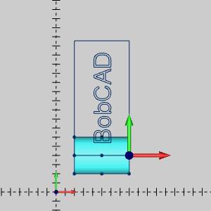
- The zero degree location of the cylindrical
part is shown next, marked by a cone at the end of the cylinder.
The second image shows the location of the machining origin on the part (that was aligned with the zero degree location of the part).

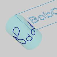
- When you simulate the feature as created
in this example, you can see the zero degree location of the part
does not contain any of the text.

- The following image shows a dimension that
is added to measure the distance between the machining origin and
the start of the letter C in the text.
Notice that this distance is measured perpendicular to the rotational axis of the part.
- The next step is to set the Zero Degree Location
parameter, in the Wrapping Group dialog box, to the distance between
the machining origin and the beginning of the letter C. (Right-click
Wrapping Group, and click Edit.
The measured distance is used to set the Zero Degree Location parameter.
When you compute the toolpath and simulate the part, the start of the letter C is now aligned with the zero degree location of the cylinder as shown in the next image.
This example shows that you can use the Zero Degree Location to change the location of the machining operation on the part.
This concludes the tutorial.