Custom Tools (Form Tools)
Introduction
This topic explains how to create custom milling or drilling tools (form tools) in BobCAM.
Custom Tool Geometry
The process of creating custom tools in BobCAM
includes creating a wireframe profile of the tool that is revolved around
the Y-axis of the
Note: You can create custom tools for any milling or drilling tool type as well as lathe drilling tools. The custom tools can then be used for any milling or drilling operations that support the tool category in which the tool is made.
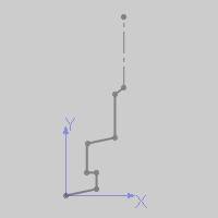
There are a few key points to creating the geometry for custom tools:
- You can use line, arc, or spline entities.
- Create a
- You only need to draw half of the profile as the software revolves
the chain around the Y-axis.
- Draw the cutting (fluted) portions of the tool using the solid
line style.
- Draw the non-cutting portions of the tool using
- The first entity (closest to X0Y0Z0) should be a solid line style.
|
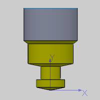
Custom Chain |
Custom Tool |
|
|
|
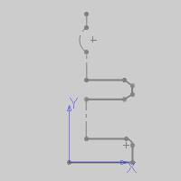
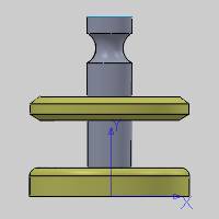
Custom Chain |
Custom Tool |
|
|
Assigning Custom Tool Geometry
After defining the custom profile for a tool, you assign the geometry to the tool using the Create/Modify Tool dialog box that is accessed from the Tool Library.
-
In the CAM Tree, right-click CAM Defaults (or Mill Tools), and click Tool Library.
Note: You cannot assign custom tool geometry when accessing the Tool Library from the CAM wizards.
-
Select a tool category on the left, such as Endmill Rough, to filter the tools list.
To create a new tool, click the Add button.
To modify an existing tool, select the tool
in the tools list, and click Modify.
-
In the Create/Modify Tool dialog (titled by the selected tool category), click the Assign Tool Geometry button.
Note: After assigning custom tool geometry, the Assign Tool Geometry button changes to Remove Tool Geometry. You can use this button to remove the custom geometry and assign a new geometry profile.
Important: When selecting sketch geometry, select the sketch entities directly from the graphics area. If you select a sketch from the Feature Manager design tree, the construction geometry is removed, which may provide incorrect results.
-

When you confirm the selection, the software returns you to the Create/Modify Tool dialog box for you to finish defining the tool. A preview of the custom tool displays on the right side of the dialog box. The software automatically sets some tool parameters based on the selected profile, but you must confirm all parameters. -
Enter all tool parameters for the custom tool and click OK to finish.
Tool Data Parameters
The software automatically populates many of the tool parameters based on the custom geometry that you define, but there are two key points:
- The Corner Radius value
defaults to 0.000, so you must type the correct Corner Radius for
the tool.
- The Number of Flutes value
defaults to 4, so you must change this value to the appropriate number
of flutes for the tool (this setting affects the speeds and feeds
calculations for the tool).
- You can alter the automatically populated values as needed, but changing the values changes the toolpath calculation. This may be used to adjust the settings for the tool, for example, as it wears.
The software sets the tool parameters based on the custom tool chain
you select as follows:
- The Diameter is twice the
maximum distance of the custom chain along the X-axis.
- The Flute Length is the
maximum distance of the cutting (solid line style) entities along
the Y-axis.
- The Overall Length and Protrusion Length values are the maximum distance of the entire chain along the Y-axis.