


Emboss 2-Rail Sweep Example 1
Introduction
This tutorial explains the Emboss 2-Rail Sweep. The main focus is on using multiple cross sections successfully to achieve a desired result. Links are provided to the help topics that explain the transition types and cross section spacing options. Please complete this tutorial along with the other 2-Rail Sweep tutorials to gain a full understanding of the Emboss 2-Rail Sweep. All dialog parameters and BobART tree items are described in the Emboss2-Rail Sweep help topic.
Example File
If you are connected to the Internet, the part file for this example can be downloaded automatically by clicking the following link: Emboss 2 RailSweep Leaf Example 1.SLDPRT
Once you download and saved the zip file, extract the files on your system in an easy place to remember. You can then open the file to use with this tutorial. All files for the tutorials in this help system available for download can be found by clicking on the following link: http://www.bobcad.com/helpfiles.
Part 1) Open the Example File
-
Click File > Open.
The Open dialog is displayed. -
Navigate to
-
Select Emboss 2 Rail Sweep Leaf Example 1.SLDPRT, and click Open.
The entities prepared for the example file are shown next.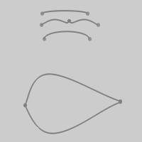
Part 2) Define the Canvas and Coordinate System
-
In the BobARTtree, right-click
 Emboss Model, and click Create/Modify Canvas.
The Canvas Definition dialog the appears. -
By default the UCS is set to
Note: To modify the canvas after it is created, right-click ![]() Emboss Model, and click Create/Modify Canvas.
Emboss Model, and click Create/Modify Canvas.
-
We use the default Origin values to place the lower-left corner of the canvas at the selected
In the Canvas Definition dialog, leave the Originvalues set to X0Y0Z0. -
In the Canvas Size group, set the X value to
-
In the Material Appearance group, click the drop down arrow for Canvas Color.
The Canvas Color drop down appears. -
Select the Lilac color.
The Canvas Color drop down disappears. -
Click OK.
The defined canvas appears in the graphics area.
-
Click Cancel to close the dialog.
Part 3) Insert the Feature
-
In the BobARTtree, right-click
Emboss Model, and click Emboss 2-Rail Sweep.
The Emboss 2 Rail Sweep dialog appears. -
Click the Colordrop downs to view the default options.
-
Select a dark green.
Part 4) Define Geometry for Rail 1 and Rail 2
-
By default the Selected Geometry list in Rail 1 group has focus.
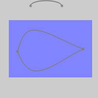
In the graphics area, select the upper geometry, as shown next.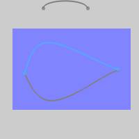
The geometry is added to the list, and the chain is added to the Profile Chain list. -
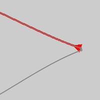
Click in the Profile Chain list to view the direction of the chain.
A zoomed in view of the chain direction arrow is shown next.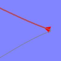
-
Click in the Selected Geometry list in Rail 2 group to give it focus.
This time, select the lower geometry.
The result should look like the image shown next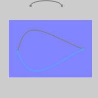
The geometry and chain direction for Rail 2 is now defined.
Tip: By clicking each of the Profile Chains, the direction of the chains will be visible. Currently they should be facing in opposing directions, which is what we want for the purposes of this example. To reverse the direction of the chain while in the dialog, click the reverse button. You can accomplish the same thing from the BobArt Tree by right-clicking Rail Geometry, and click Reverse Direction. The selected chain and direction are shown by clicking Rail-Geometryin the BobART tree.
Part 5) Define the Cross Section Geometry
-
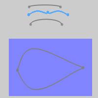
Click in the Selected Geometry list of the Cross-Section group to give it focus.
Select the lowest of the three entities located outside the canvas area, as this is the first cross section used.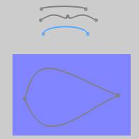
The chain is added to the list. -
Select the lowest of the three entities located outside the canvas area, as this is the first cross section used.
The chain is added to the list. -
Select the lowest of the three entities located outside the canvas area, as this is the first cross section used.
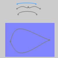
The chain is added to the list.
All entities are now defined for the 2 rails and the 3 cross sections for this sweep. The next step is to generate the sweep.
Important: The direction of the selected cross-section geometry is important because the start point of the cross section is connected to Rail 1 and the end is connected to Rail 2. The cross section is swept along the rails from the starting point to the opposite end. The outcome of any 2-rail sweep is controlled entirely by the chain direction used for each entity. For this example the direction of the cross sections does not matter because of their mirrored symmetry.
Tip: To reverse the chain direction, right-click Cross Section Geometry, click Reverse Direction. The selected chain and direction are shown by clicking Cross-Section Geometry in the BobART tree.
Part 6) Generate the Emboss 2-Rail Sweep, Edit Features, and Regenerate
-
At the bottom of the dialog, click Apply.
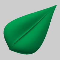
The embossed leaf is created and should appear like the next image.
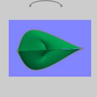
Notice that this is not the desired result.
The problem here is that the 2 rails do not share the same chain direction.
-
Click in the Profile Chain list of the Rail 1 group to view the direction of the chain.
Tip: The emboss can be hidden by right-clicking Emboss Model and selecting Blank/Unblank.
-
This chain direction is not desired.
Click the Reverse Direction button next to the list.
The chain direction is now from left to right as shown next.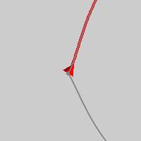
-
Click Apply again.
The embossed model should now appear as shown next.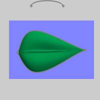
Tip: Every time that you change a 2-Rail Sweep parameter in the dialog, click Apply to see the result. You can also update items in the BobArt Tree. When this is done, right-click ![]() Emboss Model, and click Regenerate to see the changes reflected in the model.
Emboss Model, and click Regenerate to see the changes reflected in the model.
The model shown from the side view.
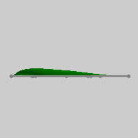
The elevation, or height, of the previous image is a result of using Scale Cross Section Based on Width. When this option is used, the entire cross section (width and height) is scaled to fit between the rails. When the check box is cleared, only the cross section width is scaled and the height remains the same. This means that the sweep height is controlled by the actual height of the cross section geometry. This is shown next.
-
Click to clear the
 Scale Cross Section Based on Width check box, and click Apply.
The sweep should appear as shown next.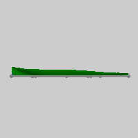
Notice in the previous image, the height changes along the sweep. The height on the left side is the same as the height of the first cross section. The height on the right side is the same as the height of the last cross section. The same is true for the middle, with the height in between cross sections blended together.
When using three or more cross sections, the way that they are blended together is defined by the Transition Type. Find out more about the Cross Section Spacing options in the Emboss 2 Rail Sweep topic.
The cross sections can be modified further using the Cross Section Spacing options. Find out more about the Cross Section Spacing options in the Emboss 2 Rail Sweep topic. -
Click Cancel to close the dialog.
This concludes the example.