


Emboss from Image Example 1
Introduction
This help topic explains how to create an Emboss from Image feature.The entire process is explained step-by-step.Some special tips are providedafter the main portion of the tutorial which will show you how to remove an unwantedarea of the Emboss from Image feature to create a component.
This tutorial combines four examples.You learn how to create an Embossfrom Image, how to Vectorize geometry (Black and White Strategy), howto use Smoothing, and how to Save As a Component/STL.You can use the links at the top right of this page to navigate to each sectionif you are not completing the entire tutorial.
Example File
If you are connected to the Internet, the part file for this example can be downloaded automatically by clicking the following link: Emboss fromImage Example 1.sldprt
Once you download and saved the zip file, extract the files on your system in an easy place to remember.You can then open the file to use with this tutorial.All files for the tutorials in this help system available for download can be found by clicking on the following link: http://www.bobcad.com/helpfiles.
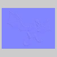
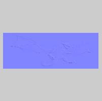
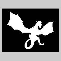
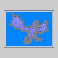
The images in the zip file needed for the Emboss from Image example, Dragon Black and White.png and DragonBAS.png, are shown next.


Example 1: Emboss from an Image
Part 1) Define Canvas
For this example, you can open the Embossfrom Image Example 1.
-
In the BobARTtree, right-click
 Emboss Model, and click Create/Modify Canvas.
 -
In the Opendialog, navigate to the folder in which you saved the examplefiles.
Tip: When locatingan image file, it can be helpful to show all file types in the Opendialog.This allows you to see all image files that are containedin each folder.To show all files: at the bottom of the Opendialog, click the Files of Typearrow, and at the bottom of the list, select AllFiles.
Select Dragon BAS.png and click Open.
The Canvas Definition dialog is displayed.
In this example the canvas is created with the same size as the image.
Tip: Noticethat we added the emboss feature before creating canvas.For the Embossfrom Image feature, this is a special tip that allows you to easily setthe canvas size to the same size as the image.Notice the Canvas Size Xand Y values are automatically set based on the image size.You can increase the Canvas Size values if you want to make the canvaslarger than the image file.(The canvas size can also be modified aftercreating the feature.)
Note: The origin of the canvas is the lower-left corner.You can type the coordinate values of a point in the OriginXYZ boxes to define wherethe canvas origin is located in the graphics area.This example uses the default values of X0Y0Z0 to place the canvas originat the WCS or world coordinate system.The default model color is used because the canvas and the image arethe same size.In this situation, the color of the feature will cover (mask) the canvascolor.
-
To close the dialog and create the canvas, click OK.
The Create Emboss from Image dialog is displayed.
Part 2) Add the Feature
-
In the BobARTtree, right-click
Emboss Model, and click Emboss from Image.
Part 3) Define the Feature Parameters
-
For this example, the Originvalues remain at X0Y0Z0.
As with the canvas, the image origin is the lower-left corner of theimage.
The Origin values define the position of the image in relation to thecoordinate system you created the model on. -
In the CanvasSize group, notice that the XSize and Y Size valuesare automatically set based on the image size.
The Z Depth uses a defaultvalue of 0.100.
This defines the maximum height of the feature and it is not guaranteedto be exactly the specified value.(The information in the image definesthe final result. -
Click in the Namebox, and type My at the beginningof the description.
When the feature is added to the BobART tree, it is labeled My ImageEmboss 1. -
To select a color for the feature, clickColor.
In the Color dialog, clickthe desired color, or define a custom color, and click OK. -
The ApplicationType, Add, is usedfor this example.
This means that the emboss is added to the model or raised in the positiveZ-axis direction. -
To create the feature using the defined values,click OK.
-
Right-click
 EmbossModel, and click Regenerate.
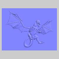
The result is shown next.
In the previous image, the maximum height in Z isless than 0.100.
The default value of 0.100 is small for this example.
The next step is to modify the Z Depth.
Part 4) Edit the Feature and Regenerate the Model
-
In the BobARTtree, right-click
 My Image Emboss 1, and clickEdit.
 -
In the CanvasSize group, set the Z Depthto 1.00.
-
To accept the change, click OK.
Notice the feature in the BobART tree.The EmbossModel icon and the  My Image Emboss 1 icon are displayed with a red x.This shows thatchanges have been made that have not been added to the model.Themodel needs to be regenerated.
 -
To add the changes to the model, right-click
Emboss Model,and click Regenerate.
Note: Everytime that you modify the parameters or the geometry/image of an embossfeature, the results are not added to the model until you Regenerate tocalculate the changes.
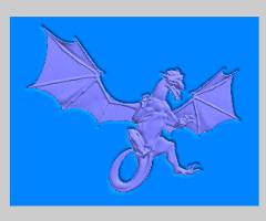
The maximum Z Depth of the feature is now 1.00.
Notice that the emboss is much more prominent thanin the previous result.
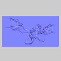
The Emboss from Image example is complete.
In the next part of this tutorial, you learn how to Vectorize an imagethat is used to create the profile of the dragon.The geometry is thenused to contain a Smoothing feature.This geometry is also used to createan emboss feature that contains all of the areas around the dragon.Aftercreating the second feature, the dragon can then be saved as a componentthat only contains the dragon, not the entire emboss from image feature.
Example 2: Vectorize - 2 Color (Black and White) Strategy
Part 1) Vectorize an Image - 2 Color (Black and White) Strategy
For this part of the tutorial, a black and white image of the dragonis loaded into the system and vectorized to create geometry that is usedlater.
-
To hide the current embossed model, right-click
Emboss Model,and click Blank/Unblank. -
In the
 BobARTtree, right-click
  Images, and click LoadImage.
Important: The Selection Manager displays for you to select the image locationand orientation.We want the vectorization result to be created ona 2D sketch so we select the Front plane.(If you do not make a selection,the Front plane is still used, but the vectorization result uses a3D sketch.) Expand the Feature Manager design tree, and select the Front plane.Click ![]() .
.
-
In the Opendialog, locate and select DragonBlack and White.png, and click Open.
Tip: When locatingan image file, it can be helpful to show all file types in the Opendialog.This allows you to see all image files that are containedin each folder.To show all files: at the bottom of the Opendialog, click the Files of Typearrow, and at the bottom of the list, select AllFiles.
The image is loaded into the graphics area with theimage origin (the lower-left corner) placed at the WCS or world coordinatesystem origin.Note that an Image feature is added to the BobART treeunder Images.(If you want to change the default location, right-click![]() Image-image name,and click Edit.)
Image-image name,and click Edit.)
-
Under
Images, right-click  Image-DragonBlack and White, and click Vectorize.
The Raster to Vector dialog is displayed. -
In the Vectorize Strategygroup, select 2-Level (Black/White)Strategy.
The Threshold Value is setto 2.(For this example, nochanges are made to the default settings.) -
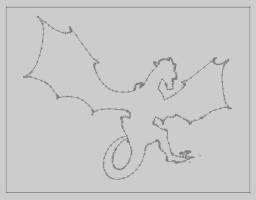
To vectorize the image using the defined parameters, click OK.
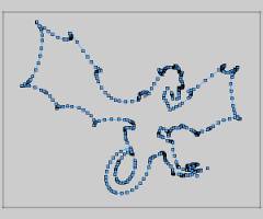
BobCAM automatically creates a sketch feature in the Feature Manager -
To hide the image and view the geometry, right-click
Image-DragonBlack and White, and click Blank/Unblank.
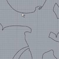
This concludes the vectorization example.The geometry that you created is used in the next three parts.
Example 3: Using Smoothing
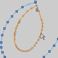
Part 1) How to Use Smoothing
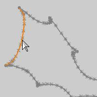
When you zoom-in to view the model up close, you can see that the resultof embossing the height-map image has left a texture/grainy appearanceon the model.This appearance may or may not be desired.For this example,we use smoothing to remove this from the model surface.The areas of themodel that we want to improve are shown next.

-
Right-click
EmbossModel, and click Smoothing. -
In the BoundaryBased Smoothing dialog, leave the default settings, andclick OK.
Zoom in, if needed,
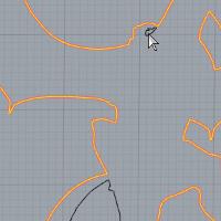
Repeat this process for the following chain.
![]()
![]() Smoothing 2, right-click
Smoothing 2, right-click ![]()
![]() Geometry,and click Re/Select.
Geometry,and click Re/Select.
To confirm the selection, click ![]()
Note: When usinga Smoothing feature, by default, the smoothing is applied to the entiremodel.(You do not have to select geometry.) When you select geometryto contain the smoothing feature, it is only applied within the selectedboundaries.
To show the embossed model again, right-click ![]() Emboss Model, and click Blank/Unblank.
Emboss Model, and click Blank/Unblank.
-
To update themodel, right-click
Emboss Model, and click Regenerate.
The result is shown next.
You can see that the surface of the model has been improved, but itcan still be improved further. -
In the BobARTtree, right-click
 Smoothing, and click Edit.
In the Smoothing Parametersgroup, change the Smoothing WindowSize to 0.100.
This increases the amount of smoothing applied. -
Click OK and Regeneratethe model, as done previously.
The result is shown next.

The surface of the modelhas been greatly improved and the smoothing is now complete.This concludesthe Smoothing portion of this tutorial.
Part 2) Create an Offset
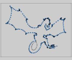
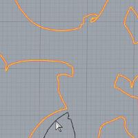
In the next part of this tutorial, you create an Emboss Regular feature.The geometry that was created from the boundary of the image is the samesize as the model/feature.Because they are the exact same size, you offsetthe geometry to assure that no artifacts are created at the edge of themodel.
-
- Right-click one of the lines making up the inner rectangle and select Select Chain.
-

-
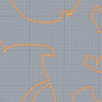
Click ExitSketch to finish the changes.
Now the boundary that is used to create the EmbossRegular feature is larger than the model.
This assures that the Emboss Regular feature coversall unwanted areas of the model.
Part 3) Create a Regular Emboss
For this part of the tutorial, a regular emboss feature is created thatcontains all of the unwanted areas of the Emboss from Image feature.Thisallows us to save only the area of the dragon as a component/stl.
-
In the BobART Manager, right-click
Emboss Model, and click Emboss Regular. -
In the Embossdialog, click Color.
Select a new color for the feature, and click OK.
In the Emboss dialog, click OK.(The parameters for this feature are not important, so the defaultvalues are used.) -
Under
 Regular Emboss 3 - Add, right-click
 Geometry,and click Re/Select.
 -
To confirm the selection, click

-
To add the changes to the model, right-click
Emboss Model, and click Regenerate.
The model now containstwo emboss features, the original Emboss from Image and the Regular Embossthat was added to surround the dragon emboss.When you save an individualemboss as a component, only the area defined by the selected feature issaved.Because the Regular Emboss covers all of the area around the dragon,it is not included when saving the Emboss from Image as a component/.stlfile.
Part 4) Changingthe Model Resolution
When the canvas is createdfor emboss features, the Resolution is automatically set based on thesize of the canvas.You can increase the Resolution some to help improvethe model appearance.You may otherwise want to lower the resolution toachieve a different appearance or to conserve system resources duringthe creation process.
Tip: The Resolutionparameter that is found in the Canvas Definition dialog is the DPI,or dots per inch, of the model.When increasing the resolution, you mustremain within reasonable limits to avoid running out of system resources.Larger resolutions require more processing power and may not be beneficialin the end result when machining the model.The level of detail in themodel only needs to match the level of detail with which it is machined.
-
In the
BobARTtree, right-click Emboss Model, and click Create/Modify Canvas. -
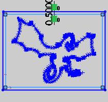
In the CanvasParameters dialog, notice the value in the Resolutionbox.
For this example, the resolution is currently
Just to see how the resolution is updated, in the CanvasSize group, change the Xvalue to 20.00, and pressTab.
The resolution is updated based on the canvas size.
(Change the X value back to18.2361.) -
In the Resolutionbox, type 125.
-
To close the dialog, click OK.
-
To update the model, right-click
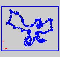
EmbossModel, and click Regenerate.
(Calculation times increase when the resolutionis increased.)
The increased resolution for this exampleactually starts to cause a grainy appearance to return, which was removedearlier by the Smoothing feature.(Increasing the Resolution creates amore detailed model.In this case, the increase does not improve the appearanceof the model.)
Before saving the component in the next part, changethe Resolution back to
Example 4: Creating a Component (IndividualFeature)
Part 1) Create a Component (Save As Component/STL)
The BobART module now includes the ability to save individual embossfeatures (or the entire model) as a component.Saving as a component meansthat the feature (or model) is saved as an .stl file.The component canthen be used to create an Emboss from Component feature.The followingsteps are used to create a component from a single feature.
-
In the
BobARTtree, right-click the top level item of the feature.
For this example, right-click My Image Emboss 1, and clickSave as Component/STL. -
In the STLSave Option dialog, click OK.The default tolerance value is used.
Tip: You candecrease the tolerance (make the value smaller) to create a more accuratemodel if necessary.However, decreasing the tolerance increases the sizeof the saved file, and it may not actually be necessary (meaning thatit doesn't improve the machining of the part).The default tolerance isa good starting point.You can increase the tolerance (for example, to
-
In the Save Asdialog, select the folder in which you would like to save thecomponent.
-
In the File Namebox, type the name of the component.
For this example, type MyDragon Component. -
To save the file, click Save.
The result of the component is shown next.(The component was openedin a new file to show the result.)
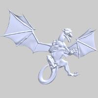
The component is finished.This concludes the How to Create a Componentportion of this tutorial.
The component is used in the How to Create an Emboss from Componenttutorial.
To learn how to save the entire model as a component, view How to SaveWhole Emboss As Component/STL.
Important Information
This section explains why the process used in this example was necessaryto create the dragon component from the Emboss from Image feature (usingonly a specific area of the feature).
It is important to understand why the process used in this tutorialwas applied to remove the areas around the dragon.The BobART module nowincludes the ability to remove the non-embossed areas of an embossed model.This option, Remove Non-Emboss Area, is found in the Canvas Definitiondialog.This option can remove excess canvas (that is larger than theEmboss from Image feature), however, it does not have an effect on theEmboss from Image feature itself, because the entire area of the imageis a part of the emboss.
Another feature in BobART is the ability to create components usingthe entire model (Save Whole Emboss As Component/STL) or individual embossfeatures (Save as Component/STL).The Save as Component/STL option savesonly the area defined by the selected feature.Any additional emboss containedwithin the same area is not included in the component.This is the reasonthat the Regular Emboss was added to the embossed model.The Regular Embossfeature covered all of the undesired areas around the dragon.When theEmboss from Image feature is saved as a component/.stl file, none of theareas contained in the regular emboss are included in the component.
Related Topics
How to Create anEmboss from Component