


Multiaxis Finishing Example 1
Introduction
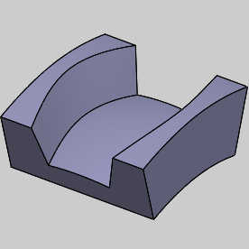
This tutorial explains how to create a Multiaxis Finishing feature with unconnected walls.
Example File
If you are connected to the Internet, the part file for this example can be downloaded automatically by clicking the following link: Multiaxis Finishing Example 1.sldprt
Once you download and saved the zip file, extract the files on your system in an easy place to remember.You can then open the file to use with this tutorial. All files for the tutorials in this help system available for download can be found by clicking on the following link: http://www.bobcad.com/helpfiles.
In the example file provided, the Tool Crib is already equipped with the necessary tools, the stock and Machine Setup are already defined, and a roughing operation has prepped the part for the finishing operations. The part is simulated using the BC_Hermie_C20U machine.
Section 1) Floor Finishing
Part 1) Add the Feature
-
 CAM Tree tab
-
Right-click
 Machine Setup and click Mill Multiaxis.
 -
In the Multiaxis Wizard, click Mulitaxis Machining.
-
Click Next>>to go to the Posting dialog box.
Part 2) Define the Posting Parameters
-
The Work Offset # is automatically set to the value defined in the Machine Setup dialog box.
You can change the value here to update the Work Offset # for the feature. -
Click Next>>to go to the Multiaxis Postingdialog.
Part 3) Define the Multiaxis Posting Parameters
-
Notice, at the top of the dialog box, that the Use Machine Settings checkbox is selected.
This means that the Multiaxis Posting parameters for the feature use the same parameters as the machine that is selected in Current Settings.
You can clear the Use Machine Settingscheck box to define the Multiaxis Posting parameters of the feature separately from the current machine settings.
An example usage is explained later. -
Click Next>>to go to the Tool page.
Part 4) Select the Finishing Tool
-
Click the Tool Crib button.
The Tool Crib dialog appears. -
Select the ENDMILL FINISH tool type on the left of the dialog to show the tapered tools available in the Tool Crib.
-
Highlight the 0.2500 Diameter tool and click OK.
The Tool Crib dialog disappears. -
Click Next>>to go to the Parameters.
Part 5) Surface paths
-
In the Pattern group, set Machining to Floor finishing.
-
In the Sorting group, change the Cutting Method to Spiral.
-
In the Stepover group, change the Maximum stepover to 0.02.
Part 6) Part definition
-
Click the Part definition tab.
-
Click the ellipses button next to Part surfaces.
The Re/Select Geometry dialog appears. -
Select the check box for Select whole bodies and select the model.
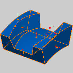
-
Click OK.
The Mill Multiaxis Wizard returns. -
Click the ellipses button next to Floor surfaces.
The Re/Select Geometry dialog appears. -
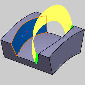
Select the bottom of the part as seen in the image below.
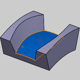
-
Click OK.
The Mill Multiaxis Wizard returns. -
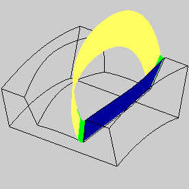
Click the ellipses button next to Wall surfaces.
The Re/Select Geometry dialog appears. -
Select the walls of the part as seen in the image below.

-
Click OK.
The Mill Multiaxis Wizard returns. -
Click Compute.
Part 7) Simulation
For more help using simulation, view Getting Started with Simulation.
-
To view the program, in the Quick access menu of the CAM Tree, click
 Simulation.
 -
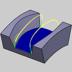
Click Play to view the Roughing operation in simulation.
This will allow you to ensure this operation is free of collisions.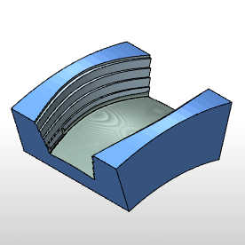
-
To close simulation, in the
 Exit Simulation.
Section 2) Wall Finishing
Part 1) Copy and Paste the feature
-
In the CAM Tree, right-click the Feature Multiaxis and select Copy with Geometry.
-
Right-click the feature again and select Paste.
-
Right-click the feature that was copied and select Rename.
-
Update the name to Floor Finish and press Enter.
Part 2) Adjust the Parameters and Compute
-
Right-click our pasted feature and select Edit.
The Mill Multiaxis Wizard appears. -
Click Parameters in the tree on the left.
-
In the Pattern group, update Machining to Wall finishing.
-
In the Sorting group, change Cutting Method to One way.
-
Click Compute.
An error message appears:
Exception raised in calculation routine (There are more than two unconnected meshes given to t geodesic. The mesh - fixer or offseter failed or there are actually two separate meshes.) -
Click OK.
This error is due to the fact that we have two unconnected wall surfaces selected.
Part 3) Update the Geometry
-
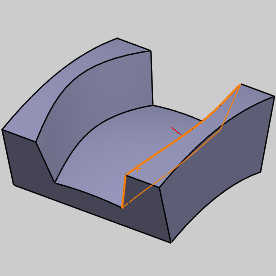
Expand the geometry folder of the feature, right-click Wall Surface and select Re/Select.
Deselect one of the wall surfaces.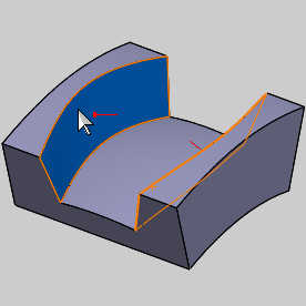
-
Click OK.
-
Right-click the feature and select Compute All Toolpath.
Part 4) Simulation
-
To view the program, in the Quick access menu of the CAM Tree, click
Simulation. -
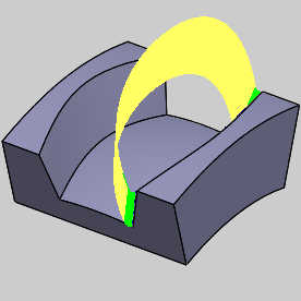
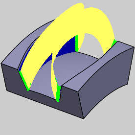
Click Play to view the Roughing operation in simulation.
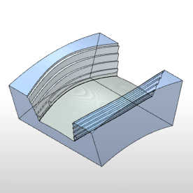
In this case we can see the wall is finished nicely without gouges. -
To close simulation, in the
Exit Simulation. -
In the CAM Tree, right-click the Feature Multiaxis feature, and click Blank/Unblank Toolpath.
-
You can also click the small arrow next to the feature to collapse it.
-
In the Filemenu, click Save.
Part 5) Copy and Paste the feature
-
In the CAM Tree, right-click the Feature Multiaxis and select Copy with Geometry.
-
Right-click the feature again and select Paste.
-
Right-click the feature that was copied and select Rename.
-
Update the name to Wall Finish 1 and press Enter.
Part 6) Adjust the Parameters and Compute
-
Expand the Geometry folder, right-click Wall Surface and select Re/Select.
The Re/Select Geometry dialog appears with the current geometry already in the list.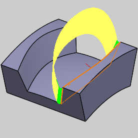
-
Right-click in the Selected Items list and select Clear Selections.
-
Select the other wall surface.
-
Click OK.
-
Right-click the feature and select Compute All Toolpath.
-
Click OK.
Part 7) Simulation
-
To view the program, in the Quick access menu of the CAM Tree, click
Simulation. -
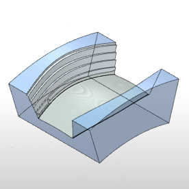
Click Play to view the Roughing operation in simulation.
In this case we can see the wall is finished nicely without gouges. -
To close simulation, in the
Exit Simulation. -
In the CAM Tree, right-click the Feature Multiaxis feature, and clickBlank/Unblank Toolpath.
-
You can also click the small arrow next to the feature to collapse it.
-
Right-click the feature and select Rename.
-
Update the feature name to Wall Finish 2 and press Enter.
-
In the Filemenu, click Save.
This concludes the example.
Related Topics
How to Create a Multiaxis Roughing Operation