Parameters
Introduction
This topic explains the Parameters page of the Advanced Rough operation found in the 3 Axis Wizard. The Advanced Rough operation provides a powerful roughing strategy with three cut patterns: an offset pattern, parallel pattern, and a high-speed machining pattern with automatic tool engagement control. Intermediate Slices, Rest Roughing, and Flatlands detection can be used as well as many other controls explained in this topic.
Operation Stock
The Advanced Rough operation always uses a stock recognition for the toolpath calculation. By default, the stock definition from the Stock Wizard is used. You can also specify the stock to use by assigning geometry to the Operation Stock item in the CAM Tree. Operation stock allows you to remove unnecessary air cutting from the operation by passing stock for only the area that you want to cut. There are no settings needed in the wizard to use stock recognition for the Advanced Rough operation. The stock definition from the Stock Wizard is always used unless you assign Operation Stock.(View Selecting Operation Stock for more help.)
Tip: You can use simulation to save the stock model as an .stl file, which can then be used as Operation Stock. To learn more, view How to Save Simulation Stock as STL.
 Parameters
Finish
-
Depth of Cut - the stepover distance for the toolpath contours.
-
(Climb) Stepover - the distance between each pass. When Zig Zag is selected for the pattern, this will be read as Climb Stepover to allow a variance between the climb and conventional passes.
-
 Conventional Stepover
- When Zig Zag is selected for the pattern you will be able to
select this check box to list a different value for the Convention
pass than has been listed for the Climb Stepover.
Conventional Stepover
- When Zig Zag is selected for the pattern you will be able to
select this check box to list a different value for the Convention
pass than has been listed for the Climb Stepover.  Conventional
Stepover - Leaving this check box cleared will leave both
climb and conventional setup to the value entered Climb Stepover.
Conventional
Stepover - Leaving this check box cleared will leave both
climb and conventional setup to the value entered Climb Stepover.
-
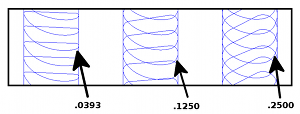
Num. of Intermediate Steps - the number of intermediate slices to be added between each step in the Z-axis.
-
-
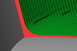
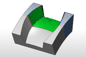
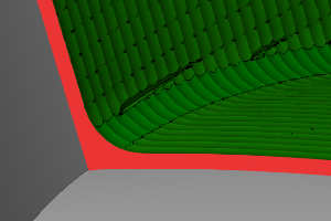
Intermediate slices can be added to roughing toolpath to reduce the staircase effect.
-
-
Less material remains for smaller tools while rest-roughing
-
Uniform thickness for semi-finishing toolpaths
-
Uniform tool load on semi-finishing tools
-
More stock removal with larger tools with reduction in number of steps
-
Reduction in Rough machining time
-
-
Intermediate slices are rest roughed, meaning additional offset passes are added, if the stock remaining is more than the specified step over, to avoid excess load on the cutter.
-
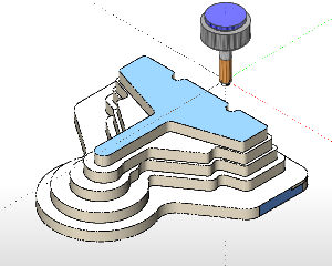
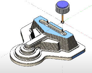
Following is an image of a part being roughed without the intermediate slices followed by the an image after adding two intermediate slices.
-
-
Machining Tolerance - the amount of variation allowed for creating the toolpath for the feature. The accuracy of the toolpath does not exceed this range.
Note: The following parameter is only available when using the Adaptive Roughing pattern.
-
Minimal Curvature Radius - determines the smallest radius used in the toolpath motion. This value must be greater than zero, but be aware that if you set this value too high, no toolpath is created. This parameter is useful, for example, to determine how far into a corner the toolpath can reach.
-
 Cut Holes - extends the toolpath
into any holes that may be present in the surface.
Cut Holes - extends the toolpath
into any holes that may be present in the surface. -
 Ignore Holes - does not place the
toolpath into any holes and treats the surface as if it is continuous
and unbroken.
Ignore Holes - does not place the
toolpath into any holes and treats the surface as if it is continuous
and unbroken.
Depth Options
-
Automatic - the depth is automatically
set using one of three options.
-
-
Min/Max from Machining Surfaces
- the toolpath is created using the total depth of the selected
geometry.
-
Min/Max from Stock
- the toolpath is created using the total depth of the defined
stock geometry.
-
Min/Max from Both - the toolpath is created using the
total depth of the defined stock and the selected feature geometry.
-
-
User Defined - the depth is set
using the Top of Job and Bottom of Job values.
-
Top of Job - sets the highest Z location for toolpath
as the top of stock. Top of Job -
allow you to specify the highest Z location for toolpath in this operation.
Select the check box and type a value to define a plane for the top
of job.
-
Pick - hides the Wizard to allow you to select geometry to associate as the Top of Job.
-
Bottom of Job
- sets the lowest Z location for
toolpath as the bottom of stock. Bottom of Job -
allows you to specify the lowest Z location for toolpath in this operation.
Select the check box and type a value to define a plane for the bottom
of job.
-
Pick - hides the Wizard to allow you to select geometry to associate as the Bottom of Job.
Note: The Bottom of Job and Top of Job values are in reference to the machining origin (Machine Setup coordinate) of the part.
Allowance
The Allowance settings are used to define the rest material, or the amount of material remaining after this operation to be removed by the next operation, in one of two ways. These options offset the model geometry to calculate the toolpath. You can use positive or negative values to leave extra material or cut deeper than the model geometry, respectively.
Offset Type
The Offset Type determines if the allowance is applied to the entire model or separately for the bottom and sides of the part. Select one of the following options and then type the allowance value in the available allowance boxes.
-
Global - applies a single allowance value to the entire model using the Allowance XYZ value.
-
Allowance XYZ - is the amount of material left on the entire model (XYZ).
-
Side and Bottom - allows you to specify separate allowances for the side (XY) and bottom (Z) of the part.
-
Side Allowance - is the amount of material left on the sides of the part (XY).
-
Bottom Allowance - is the amount of material left on the bottom of the part (Z).