Hole Recognition Dialog
Introduction
This topic will explain the Hole Recognition dialog, describe how to access it, explain the options found in it, will provide an example, and provide links to related topics.
The Hole Recognition dialog
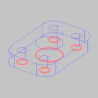
The Hole Recognition dialog allows you to select a knowledge base template to apply to selected geometry
The first step of Milling Wizards is to assign geometry for the feature.
All operations in the feature are performed on the selected geometry.
This can be a single entity or multiple entities depending on the type
of feature. The Hole features use points, arcs, cylindrical surfaces, solid edges
Navigation
To apply the Hole Recognition feature, you can either:
- In the CAM Tree, right-click the Milling Job, and select Hole Recognition.
This method will apply the Hole Recognition to all available Machine Setups in the job, and any Index Systems contained in those Machine Setups. - In the CAM Tree, right-click the desired Machine Setup, and select Hole Recognition.
This method will apply the Hole Recognition only to that particular Machine Setup, and any Index Systems contained in that Machine Setup. - In the CAM Tree, right-click the desired Index System, and select Hole Recognition.
This method will apply the Hole Recognition only to that particular Index System.
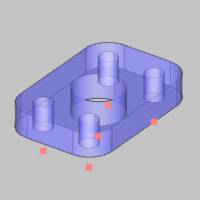
Supported Geometry Types
When selecting geometry for Hole Recognition, you can select whole
solids,
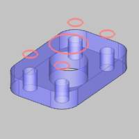
Selecting Whole Bodies
When using the Select Whole Bodies option, the software automatically creates features for all holes (or radii) found in the model. This may result in more features than desired, but you can simply deselect the extra features from the Recognized Hole Features dialog, or delete them from the CAM tree after they are created. Note that you can use the Options group to limit the hole diameters for which the software creates features. To use any other selection option, ensure the Select whole bodies option is cleared.
Cylindrical Surfaces
Selecting cylindrical surfaces allows the software to automatically set the diameter, top of feature, and the feature depth for you.
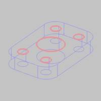
Points, Arcs, or Surface Edges
Depending on the Z-axis location of the geometry and the settings that you define, the software may automatically set the diameter, top of feature, or feature depth, but not all of them. Be sure to properly set (or confirm) all of these parameters when using these geometry types.
CAD Features
Selecting the CAD features allows the software to automatically set the diameter, top of feature, and the feature depth for you.
The Hole Recognition dialog
Knowledge Base
Use the drop down to choose a particular Knowledge Base template. Using this template will apply the rules defined in it to create the hole features. To learn more about the Knowledge Base, see the Knowledge Base topic.
Note: The last Knowledge Base template to be edited in the Knowledge Base will automatically be shown here.
Geometry
- Select Whole Bodies
 Select the check box to enable whole body selection. When
you click a part model, the entire model is selected. Single
entity selection is disabled. When using the Select Whole
Bodies option, the software automatically creates features
for all holes (or radii) found in the model. This may result
in more features than desired, but you can simply delete the
extra features from the CAM tree after finishing the wizard.
Note that you can use the Options group to limit the hole
diameters for which the software creates features.
Select the check box to enable whole body selection. When
you click a part model, the entire model is selected. Single
entity selection is disabled. When using the Select Whole
Bodies option, the software automatically creates features
for all holes (or radii) found in the model. This may result
in more features than desired, but you can simply delete the
extra features from the CAM tree after finishing the wizard.
Note that you can use the Options group to limit the hole
diameters for which the software creates features.  Clear
the check box to use standard single entity picking. This
allows you to select single sketches, edges, surfaces, or
CAD features.
Clear
the check box to use standard single entity picking. This
allows you to select single sketches, edges, surfaces, or
CAD features.
Selecting and Removing Geometry
The entities that you select in the graphics area or Feature Manager Design Tree display in the Geometry list. To remove geometry, right-click in the Geometry list to open a shortcut menu with the following options.
- Clear Selections - Removes all selections from the list.
- Delete - Removes the currently selected items from the list.
Tip: You can also remove geometry selections by deselecting entities in the graphics area
Selecting Multiple Entities in the Geometry List
The Geometry list allows for multiple selections using standard controls as follows.
-
Click
an entity name in the list to select it.
-
Hold
down theCtrl
key and click an entity to add it to or remove it from the
selection.
- After selecting one entity, hold the Shift key and click another entity to select all entities in between the first and second selections.
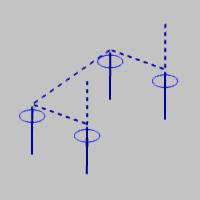
Point and Arc Usage
- Ignore Z - means that
the Z-axis location of the geometry is ignored so that
you can manually set the Top of Feature and the Feature
Depth in the wizard. This option is helpful when the selected
geometry is not the top or bottom of the hole.
- Use as Top - means that
the geometry is the Top of Feature (the top of the hole).
The software calculates the toolpath using the Z-axis
location of the geometry as the top.
- Use as Bottom - means
that the geometry is the bottom of the feature (bottom
of the hole). The software calculates the toolpath using
the Z-axis location of the geometry as the bottom.
Parameters
- Tolerance - is a selection tolerance that is used in the feature detection based on the type of selections made. For most scenarios, you should not have to change this value.
Options
The Options group allows you to set particular parameters to decide what will be created for a hole feature and what will be ignored.
- Gouge check
With this check box selected, any holes that have other surfaces in the way of their completion will be ignored. With this check box cleared, surfaces which may be gouged in order to complete a hole will be ignored, and the hole feature will be created. - Allow split face holes
With this check box selected, features will be created for holes made up of multiple surfaces. With this check box cleared, holes made up of multiple surfaces will be ignored.
Minimum Hole Diameter -
is the smallest hole diameter that is used for the current
drilling feature. Any smaller holes will be ignored.
Maximum Hole Diameter -
is the largest hole diameter that is used for the current
drilling feature. Any larger holes will be ignored.
Minimum Sweep Angle - allows you to define an acceptable range for open, or partial holes. Any holes whose start and end ranges are below the specified angle will be ignored.
Allow group
![]() With this check box selected, holes with the same diameter, but different depths or heights, will be divided into separate groups inside of the same feature.
With this check box selected, holes with the same diameter, but different depths or heights, will be divided into separate groups inside of the same feature. ![]() With this check box cleared, holes with the same diameter, but different depths or heights, will be kept as separate features.
With this check box cleared, holes with the same diameter, but different depths or heights, will be kept as separate features.
Quick Steps
In the Hole Recognition dialog:
- Select the Knowledge Base template to apply.
- Select the desired geometry.
- Adjust the Parameters as needed.
- Adjust any necessary Options.
- Click OK.
The Recognized Hole Features dialog appears.