Geometry Selection
Introduction
This topic explains the Geometry Selection page of the Lathe Wizard for an End Face feature. This topic will explain the option, provide images of example geometry, and provide a link to the next topic.
The Geometry Selection page
The Geometry Selection dialog box of the Lathe Wizard displays as seen below. This is the first page that you see when you add a feature. The first step is to assign geometry for the feature. This topic will go over how to select geometry for this feature.
Geometry Selection
|
|
|
Geometry Selection
- Select Geometry - opens the geometry selection dialog to allow you to select the
geometry from which the feature will be created. You can select
wireframe, spline geometry,

Note: For Lathe jobs, draw the profiles in the XY plane of the WCS as the machining origin (work offset) is fixed at the WCS with the machining origin Z-axis aligned to the WCS X-axis. For Mill Turn jobs, you can create the machining origin in any location, so you just need to make sure that lathe profiles are selected from the XZ plane of the machining origin.
|
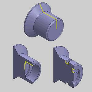
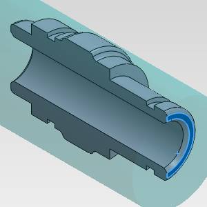
Surface Selection |
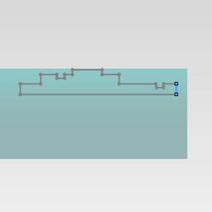
Line Selection |
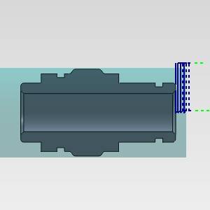
Result |
|
|
|
|
Next Topic
After assigning geometry to the feature, click Next> > to go to Feature Parameters.