 Parameters
Introduction
This topic will explain the Parameters page of the Lathe Groove Finish operation and all the options found in it. This topic will also provide a link to the next topic.
The Parameters page
The Parameters page gives you the control to tweak the pattern that has been selected on the previous page. The options available to you in this page include the depth of cut, the allowance being left, whether or not an overlap on passes is used, the corner type, which controls whether the tool rolls over corners or not, and also allows you to trim the toolpath to the stock size and shape.
Parameters
The parameters section give you control over the allowances, if any, that are left on the selected geometry
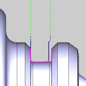
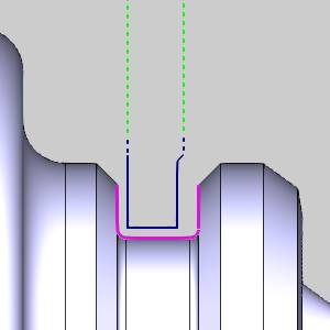
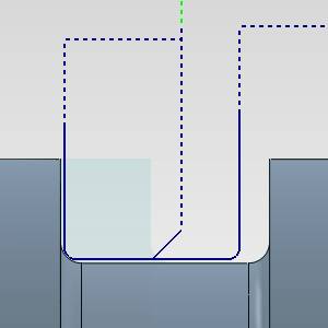
Finish Allowance - will allow you to leave material on the workpiece to be handled by another finishing pass. Setting values for the Finish Allowance will leave the last pass of this operation offset from the selected geometry by the amount entered in the available Z and X boxes.
Z
- sets the amount left in the Z direction for the finish.
X - sets the amount left in the X direction for the finish.
|
No Allowance |
Finish Allowance |
|
|
|
Chip Break
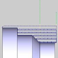
The option allows you to create minute retract moves, at user specified intervals, to aid in chip breaking.
![]() Chip Break... - With this option cleared, the toolpath will not include chip break moves.
Chip Break... - With this option cleared, the toolpath will not include chip break moves.
![]() Chip Break... -
With this option selected, the toolpath will include chip break moves that can be modified in the Chip Break dialog. Click the Chip Break button to enter the dialog.
Chip Break... -
With this option selected, the toolpath will include chip break moves that can be modified in the Chip Break dialog. Click the Chip Break button to enter the dialog.
|
|
|

|
|
Options
This group allows you to determine how the intervals between retracts should be defined.
 Length of cut - The retracts are determined by the amount of space between them.
  Time - The retracts are determined by the amount of time between them.
- Length of chip - The retracts are determined by the amount of material being removed between them.
Retract
- Retract distance - sets the length of the retract move used to break chips.
Corner Type
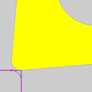
This section gives you a way to create sharp corners when moving through outside angles and corners. When system compensation is being used, the toolpath adjusts to keep the specified geometry of the tool in contact with the geometry. In the case of outside angles and corners, this causes a radius in the toolpath as the tool rounds over the geometry.
![]() Round - keeps the specified tool
geometry in contact with the geometry at all times.
Round - keeps the specified tool
geometry in contact with the geometry at all times.
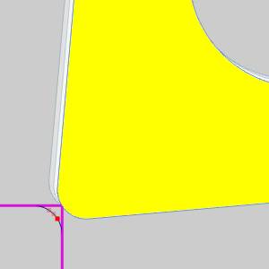
![]() Sharp - allows the tool to move
off the geometry in order to line up with the next move on the following
entity. This method eliminates the rounding over of the tool.
Sharp - allows the tool to move
off the geometry in order to line up with the next move on the following
entity. This method eliminates the rounding over of the tool.
|
Theoretical Point on Tool |
||
|
|
||
|
|
||
|
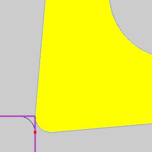
Rounded Corner |
||
|
|
|
|
|
|
|
|
|
Sharp Corner |
||
|
|
|
|


Bounds
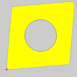
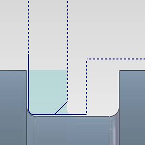
The Bounds section give you the ability to trim the toolpath to the bounds set by the Operation Stock.
![]() Trim to Stock - With this option cleared, the toolpath will not be trimmed.
Trim to Stock - With this option cleared, the toolpath will not be trimmed.
![]() Trim to Stock -
With this option selected, the toolpath that extends beyond
the Operation Stock will be trimmed away.
Trim to Stock -
With this option selected, the toolpath that extends beyond
the Operation Stock will be trimmed away.
|
|
|
|
|
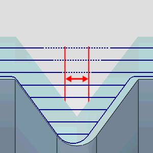
Extension - When trimming causes gaps in the toolpath, Extension closes the gap from each side by the amount entered. This is done to create a lead out of, and back into the material.
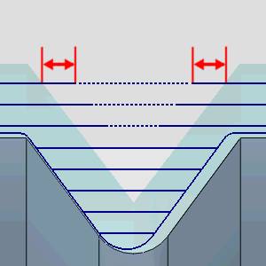
Maximum Gap - sets the limit on the area to feed across when no stock is detected.
Next Topic
Once the Parameters have been set, click Next >> to continue to the Rapids page.