 Patterns
Introduction
This topic will explain the Patterns page of the Lathe Groove Finish operation and all the options found in it. This topic will also provide a link to the next topic.
The Patterns page
The Patterns page gives you control over the pattern of the cut, and the compensation that will be used to complete the operation.
Pattern
Will allow you to select between a one directional semifinish, or a semifinish that forces a downward cut.
|
Basic Finish |
Force Down Cutting |
Force Down Cutting with Overlap |
|
|
|
|
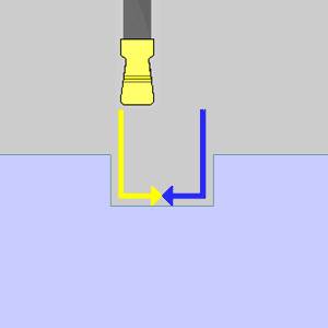
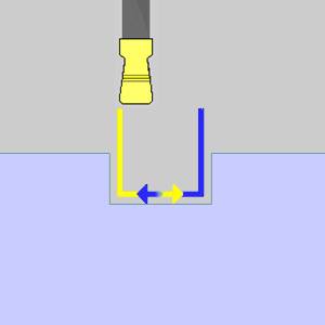
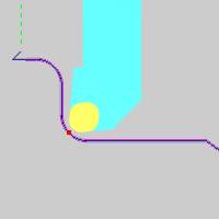
![]() Force Down Cutting -
selecting this option will force the semifinish to be cut from each side
of the groove one at a time, each in a downward direction, to the middle
of the groove. Adding an overlap will set each pass to go past the center
of the groove half the specified amount.
Force Down Cutting -
selecting this option will force the semifinish to be cut from each side
of the groove one at a time, each in a downward direction, to the middle
of the groove. Adding an overlap will set each pass to go past the center
of the groove half the specified amount.
Overlap - sets the total distance between the two passes exits, not including any leads that are uses.
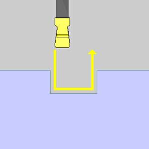
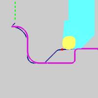
![]() Basic Finish - sets
the semifinish pass to one single direction.
Basic Finish - sets
the semifinish pass to one single direction.
Compensation
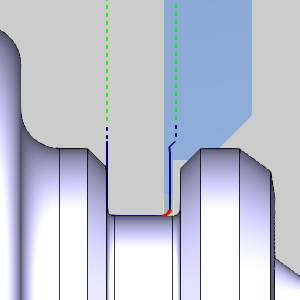
Each tool has a theoretical point placed on it as seen in red in the animation below. In the case of tools with a radius of any size, this point is not actually on the tool, but on the horizontal and vertical intersections of the radius. It is this point that the toolpath plots out. When compensation is used, it is designed to place the actual tool and not just its theoretical point on the geometry. This can be accomplished with System Compensation, Machine Compensation, or a combination of the two.
-
System Compensation
This
specifies whether or not the system compensates for the insert geometry
and the tool nose radius.
-
Off - the selected geometry is used as the program path; Machine Compensation should be used.
-
On with Collision Detection - the system compensates for the tool nose radius and the insert geometry and avoids any detected collisions.
| System Compensation: | ||
|
Theoretical Point |
Off |
On with Collision Detection |
|
|
|
|
![]() Use Tool Holder - no collision check is done on the holder.
Use Tool Holder - no collision check is done on the holder.
![]() Use Tool Holder - a collision check is done on the holder, and the toolpath is adjusted to ensure the tool holder does not collide with the geometry.
Use Tool Holder - a collision check is done on the holder, and the toolpath is adjusted to ensure the tool holder does not collide with the geometry.

-
Machine Compensation
Outputs the necessary codes to allow for the user to enter compensation data at the machine. When this is done, the machine will alter the path based on the data entered at the machine. This can even be used in combination with System Compensation in order to compensate for tool wear or other unforeseen variables. -
Off - nocompensation commands are output in the posted program.
-
Comp Left / G41 - outputs the left compensation command in the posted program.
-
Comp Right / G42 - outputs the right compensation command in the posted program.
Next Topic
Once the Pattern variables have been set, click Next> > to continue to the Parameters page.