Gouge check: Port Machining
Introduction
This topic will explain the options found in the Gouge check tab of the Port Machining operation.
Gouge check
The Tool axis control tab allows you to set clearance types and values as well as set check surfaces and set the check tolerance.
Clearance type
-
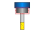
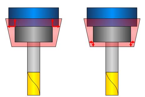
 Cylindrical - applies a cylindrical offset to the holder, arbor and shaft.
-
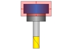
 Conical - applies a conical offset to the holder, arbor and shaft.
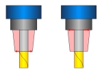


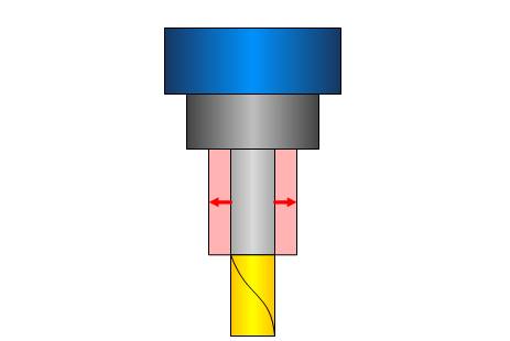
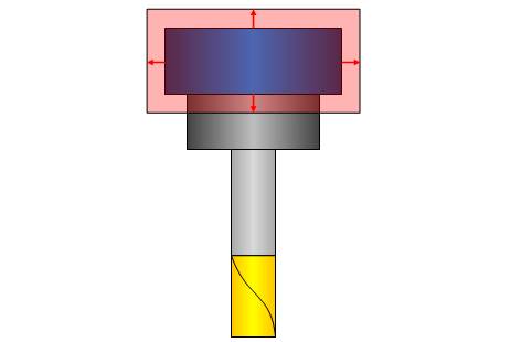
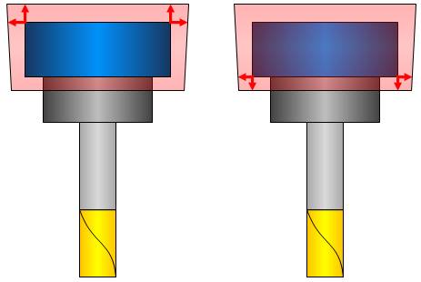
Clearance values
The available Clearance values define the clearance for the Shaft, Arbor, and Holder. While there is a single value available when the Cylindrical Clearance type is used, there are two values, defining the top and bottom, when a Conical Clearance value is used.
|
|
|
|
|---|---|---|
|
|

|
|

|
|
|
|
|
Important: These values should be greater than the allowance being left on the surfaces.
Angular clearance
The Angular clearance creates a conical clearance area around the tool. The angles origin varies based on the type of tool selected. In the case of a flat end mill, the angle will originate from the bottom diameter of the tool. In the case of an end mill with a radius, the angle will originate from the tangency of the radius.
| End Mill | Ball End Mill |
|---|---|
Note:
When Angular clearance is used in conjunction with the regular clearance values, clearance values will extend the area of angular clearance.
![]()
![]()
- Check against machining surfaces
 - The toolpath is checked to verify that no machining surfaces are gouged.
  - The toolpath is not checked for gouging machining surfaces. This can be helpful if the model has surfaces that will not exist on the finished part.
 - Check surfaces
- Allows you to select additional surfaces which are considered for collision checking in the toolpath calculation. Collision avoidance depends on the selected tilting strategy. For example, if the selected strategy is 3-axis, any contact between the check surface and the tool will be avoided by trimming the affected toolpath segments. If the tilting is set to 5-axis, the system first tries to tilt the tool away from the check surfaces and uses trimming as if tilting no longer helps. Check surfaces are typically fixtures or clamping systems that interfere with machining. - The toolpath is not checked against additional surfaces. -
Check tolerance - sets the tolerance for the above checks.