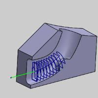
Surface paths: Port Machining
Introduction
This topic will explain the options found in the Surface paths tab of the Port Machining operation.
Surface paths
The Surface paths tab allows you to control the pattern of the cuts, the part definition, the area being cut, as well as the surface quality, depth step and stepover.
Pattern
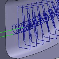
- Roughing- creates a full pocket of multiple slices and layers through the port.
- Offset - handles the roughing with a pattern offset from the walls.

- Adaptive - creates a high-speed machining operation with automatic tool engagement settings. When this option is selected, the Desired stepover and Minimal Curvature Radius options are added to the Stepover group. In addition, the Link clearance height is added to the Advanced parameter group in the Link page of the wizard.


- Offset - handles the roughing with a pattern offset from the walls.
- Finishing along- creates a pattern that moves back and forth along the length of the port.

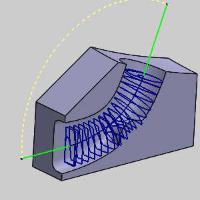
- Finishing around - creates a single spiral to finish the port surface.
- Rest roughing - handles material left from a larger tool.
- Offset - handles the rest roughing with an pattern offset from the walls.
- Adaptive - creates a high-speed machining operation with automatic tool engagement settings. When this option is selected, the Desired stepover and Minimal Curvature Radius options are added to the Stepover group. In addition, the Link clearance height is added to the Advanced parameter group in the Link page of the wizard.
- Offset - handles the rest roughing with an pattern offset from the walls.
Part definition
- Machining surfaces - click to select the port surfaces.
- Offset - The offset is the rest material left on the port surfaces. This can be used for a roughing toolpath where rest material must be left for finishing.
- Offset - The offset is the rest material left on the port surfaces. This can be used for a roughing toolpath where rest material must be left for finishing.
- Automatic spine
 - The system tries to create a spine to use for the operation. In more complex ports, this option may not be viable. When used with an offset, an automatic spine will generate cuts only in valid zones.
 - The Spine button becomes available allowing you to select a custom spline.
 - Spine - When using a drawn spine, be sure the spine is always positioned inside the port, and that the tool can always fit between the port wall and the spine. If the spine is too short, all the machining surfaces may not be reached.
- Spine - When using a drawn spine, be sure the spine is always positioned inside the port, and that the tool can always fit between the port wall and the spine. If the spine is too short, all the machining surfaces may not be reached.
- Stock - When Rest roughing is used this option will allow you to define the stock to be utilized.
- Offset - The offset is the rest material left on the port surfaces. This can be used for a roughing toolpath where rest material must be left for finishing.
- Offset - The offset is the rest material left on the port surfaces. This can be used for a roughing toolpath where rest material must be left for finishing.
Stock definition parameters
-
Stock type - determines the area to be roughed. Select either:
-
Surfaces - the stock type is set to the surfaces option.
-
Stock surfaces - click this button to launch the geometry selection dialog which allows you to select surfaces to use as the stock, or an stl file.
-
-
-
Tolerance - sets the tolerance on the stock to apply the rest roughing to.
-
 Shrink - allows you to apply a negative allowance on the specified stock.
 -
 Expand - allows you to apply a positive allowance on the specified stock.
Area
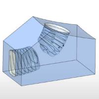
- Output type - determines which portion of the port is machined.
- Both - applies toolpath to both ends of the port.
- Top - applies toolpath to the top of the port only.

- Bottom - applies toolpath to the bottom of the port only.
- Both - applies toolpath to both ends of the port.
- Advanced - Click the Advanced button to launch the Advanced option for Port Machining Area dialog.
Advanced options for Port Machining Area
Top Area
-
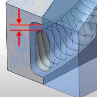
Edge rolling - Edge rolling creates a toolpath extension such that the tool approaches and enters the port smoothly and gradually. Without edge rolling, the tool starts with the center-point height of the tool. With edge rolling, the tool starts on a higher level above the boundary of the port. This feature reduces the cutting load at the beginning of the machining process. The top and bottom side sections can be optimized independently.
-
% - Use a distance in percent from the tool radius to define the amount of extension. When the distance is 100% (maximum value), additional cuts are defined at a distance equal to the tool radius. Lower values reduce the number of additional cuts.
-
|
|
|
|
|

|

|

|
Lead in/out
-
Approach Ramp - While approaching port geometry, a gradual smooth ramp is applied. The tool performs a continuous motion around the port geometry while gradually increasing the offset to the port. This option can only be applied if the approach position is inside the port geometry.
-
Retract Ramp - While retracting from the port geometry, a gradual smooth ramp is applied. The tool performs a continuous motion around the port geometry while gradually decreasing the offset to the port. This option can only be applied if the retract position is inside the port geometry.
Bottom Area
-
Edge rolling - Edge rolling creates a toolpath extension such that the tool approaches and enters the port smoothly and gradually. Without edge rolling, the tool starts with the center-point height of the tool. With edge rolling, the tool starts on a higher level above the boundary of the port. This feature reduces the cutting load at the beginning of the machining process. The top and bottom side sections can be optimized independently.
-
% - Use a distance in percent from the tool radius to define the amount of extension. When the distance is 100% (maximum value), additional cuts are defined at a distance equal to the tool radius.
-
|
|
|
|
|

|

|

|
Lead in/out
-
Approach Ramp - While approaching port geometry, a gradual smooth ramp is applied. The tool performs a continuous motion around the port geometry while gradually increasing the offset to the port. This option can only be applied if the approach position is inside the port geometry.
-
Retract Ramp - While retracting from the port geometry, a gradual smooth ramp is applied. The tool performs a continuous motion around the port geometry while gradually decreasing the offset to the port. This option can only be applied if the retract position is inside the port geometry.
Overlapping area
-
Max.overlap distance - When the toolpath overlaps on both sides, the maximum overlap distance is used to optimize the distance between the two toolpath segments.
-
Machine to - allows you to determine how much is machined from each side of the port.
-
Midpoint - ends the cuts from the top and bottom at the middle of the port.
-
| Output type: Both | Output type: Top | Output type: Bottom | |

|

|

|
-
Max from top - cuts as far as possible from the top while ending the cuts from the bottom at the middle of the port.
| Output type: Both | Output type: Top | Output type: Bottom | |

|

|

|
-
Max from bottom - cuts as far as possible from the bottom while ending the cuts from the top at the middle of the port.
| Output type: Both | Output type: Top | Output type: Bottom | |

|

|

|
-
User defined - allows you to define custom values to define exactly where the cuts start and end from both the top and bottom. The side of the port defined as the bottom will always represent 100% (Full depth), while the top of the port will be 0% (Zero depth).
-
Top - define where the cuts from the top begin and end using percentage values.
-
Bottom - define where the cuts from the bottom begin and end using percentage values.
-
Sorting
-
Cutting method - allows you to choose between Zigzag and One way machining when using the Finishing along Pattern.
-
Zigzag- creates a toolpath with an alternating cutting direction.
-
One way - creates a toolpath that only cuts in one direction. A retract and rapid move is created at the end of each toolpath slice.
-
Direction for one way machining - when using the One Way cutting method, set the cutting direction to Climb or Conventional. This option is not available when using the Finishing along Pattern.
-
Ramp angle - The ramp angle defines the pitch of the helix when the tool plunges to the next deeper layer.
- Transform / Rotate
- With this check box cleared the operation will not create copies of itself, although a toolpath pattern can still be applied outside of the operation which includes this path. - With this check box selected the operation will create copies of itself using either rotation or translation. Click the Transform / Rotate button to set the options of the copy.
Rotate Toolpath
Orientation
-
Axis/Direction - When the toolpath overlaps on both sides, the maximum overlap distance is used to optimize the distance between the two toolpath segments.
-
X axis - rotates the copies around the X axis of the machine setup.
-
Y axis - rotates the copies around the Y axis of the machine setup.
-
Z axis - rotates the copies around the Z axis of the machine setup.
-
User defined - allows you to define a custom rotation axis for the copies. With this option selected the ellipses button appears. Click the ellipses button to define a custom point of rotation by data entry, or geometry selection.
-
-
Base point - Click the ellipses button to define a custom point of rotation by data entry, or geometry selection.
-
Number of steps - determines the total number of instances.
Rotate
-
Start angle - defines the first rotated position for the toolpath. A value of zero places the first instance on the selected geometry. Selecting a different value moves the toolpath off the selected geometry.
-
Rotation angle - defines the distance between copies.
Transform
-
Start distance - defines the first position for the toolpath along the defined Axis/Direction. A value of zero places the first instance on the selected geometry. Selecting a different value moves the toolpath off the selected geometry.
-
Stepover distance - defines the distance between copies.
Sorting
-
Sort by - defines the order of the cuts.
-
Alternate shortest connection - allows the software to move back and forth between the tops and bottoms of the copies as needed to create the shortest distance.
-
Top first - machines the top of all the copies before moving to the bottoms of all copies.
-
Bottom first - machines the bottom of all the copies before moving to the tops of all copies.
-
Surface Quality
-
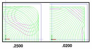
Cut Tolerance - type a value to define how accurate the toolpath is in relation to the selected geometry. Smaller values create a more accurate toolpath but also increase calculation times.
Tip: You can reduce the cut tolerance value, for example from 0.0005 to 0.005, to speed up the toolpath calculation while creating and modifying your toolpath. Once you're are happy with the result, you can then set it back to the original tolerance to calculate the toolpath before posting the output.
- Maximum distance
- With this check box cleared a maximum distance between toolpath points will not be enforced. - With this check box selected a maximum distance between toolpath points will be set and enforced. - Minimum distance
- With this check box cleared a minimum distance between toolpath points will not be enforced. - With this check box selected a minimum distance between toolpath points will be set and enforced.
Stepover
The parameters used to define the stepover change slightly depending on the selected pattern settings.
-
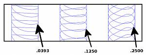
Maximum stepover - is the not-to-exceed distance between each toolpath slice.
-
Cusp height - is used to define the stepover value using a cusp height instead of a distance when using a ball endmill with the Offset pattern.
-
Desired stepover - is the optimal stepover for the feature which is used as much as possible. This option is available when using the adaptive pattern.
-
Minimal Curvature Radius - determines the smallest radius used in the toolpath motion when using the adaptive pattern. This value must be greater than zero but be aware that if you set this value too high, no toolpath is created. This parameter is useful, for example, to determine how far into a corner the toolpath can reach.
-
Depth Step - sets the distance between the cut depths when using the roughing patterns.