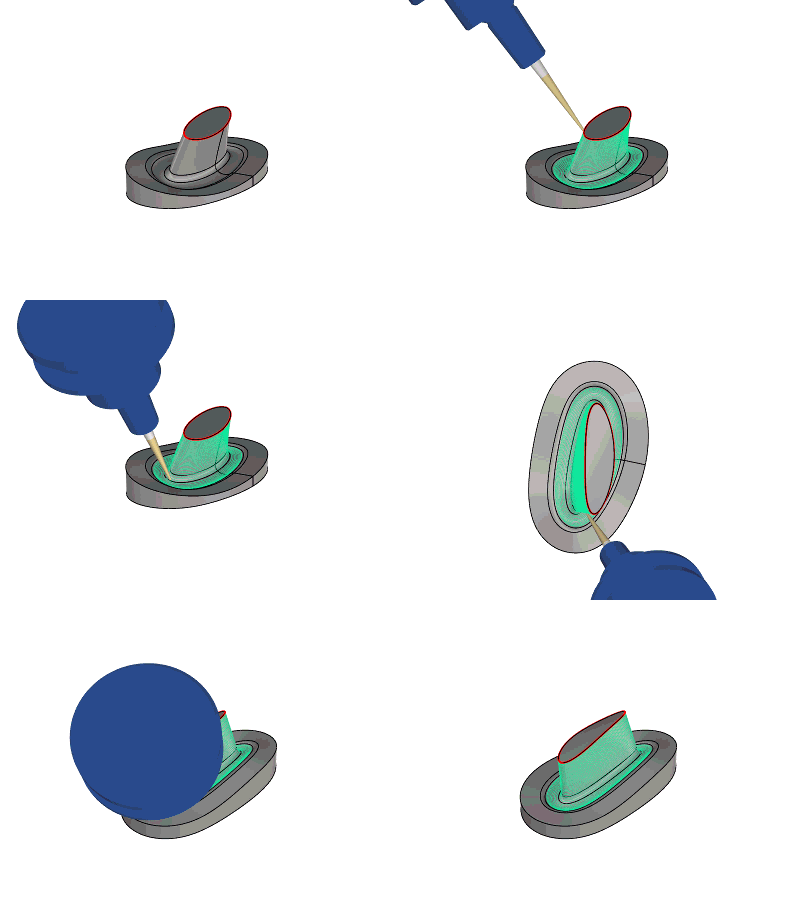
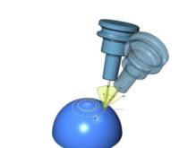
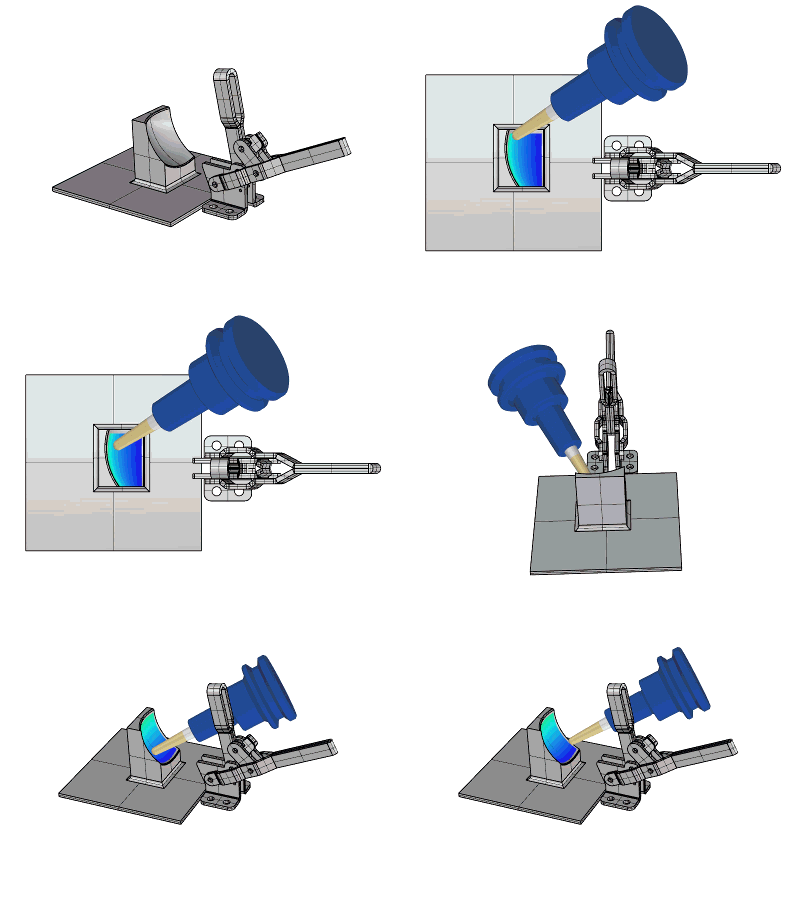
Tool axis control
Introduction
The Tool Axis Control tab of Multiaxis Wizard defines the tool axis orientation parameters. This help topic is designed as a reference to all of the parameters that can be found in this section. Not all of the parameters are applicable to all Multiaxis features.
Tool Axis Control Parameters
Many of the Tool Axis Control parameters change based on the selected tilting strategy (Tool axis will...). Any parameters that are not explained in this help topic can be found using the following links to the appropriate tilting strategy help topic.
-
Output Format - allows you to convert a multiaxis toolpath to 3- or 4-axis output. To learn more, view the Output Format help topic.
-
Maximum Angle Step - defines the maximum allowed angle change between two toolpath positions. To learn more, view the Maximum Angle Step help topic.
Tilting Strategies
-
Tool Axis Will - select from one of the following Tilting Strategies.
Not Be Tilted and Stays Normal to Surface
Not Be Tilted and Stays Normal to Surface - uses the surface normal direction to define the tool axis orientation. When using this option, the tool is always tilted normal to the tangent of any point on the surface.
Tilted Relative to Cutting Direction
Tilted Relative to Cutting Direction - provides options to tilt the tool using the following parameters that are based on the cutting direction. Without addition angles defined, the tool axis orientation uses the surface normal direction. The following two parameters are in addition to this orientation.
- Set side tilt by - This option is not available with a flat endmill. Two parameters define the side tilt:
- Angle - the user chooses the side tilt angle and the algorithm defines the tool contact point.
- Contact point - the user chooses the contact point on the tool and the algorithm defines the angle.
- Contact point definition - When Contact point is selected, the Contact point definition becomes available. The contact point can be defined in two different ways:
- By height - The contact point is defined by the distance from the tool tip to the contact point in the tool axis direction. The distance is normalized with the flute length such that the user is allowed to enter values between 0 and 1. A value of 0 means that the contact point is directly on the tool tip.
- By line parameter - The contact point is defined by the distance from the tool tip to the contact point along the tool profile. The distance is normalized with the length of the considered profile section such that the user is allowed to enter values between 0 and 1. A value of 0 means that the contact point is directly on the lower end of the considered profile section.
- Considered profile section When By line parameter is selected for the Contact point definition, the Considered profile section becomes available :
- Full profile - The entire profile from the tip to the top of the flute.
- Barrel section - Only the profile radius on the tool flank.
- Convex tip section - Only the radius on the tool front face.
- Considered profile section When By line parameter is selected for the Contact point definition, the Considered profile section becomes available :
Note: The Barrel section, and Convex tip section are only available for Barrel Mill tool types. For more information, see the Barrel Mills topic.
- Use negative side tilt - The tool can be aligned on the defined contact point using a positive and a negative side tilt angle with the same absolute value. By default, the positive angle is used. Select this check box to use the negative side tilt angle.
- Height in percent of flute length / Line parameter - the name of this option changes depending on the option chosen for the Contact point definition option. The contact point can either be defined by a single value that is used along the whole contour or the user can set an additional value. In the later case, the contact point moves gradually along the contour from the first to the second value.
- Contact point definition - When Contact point is selected, the Contact point definition becomes available. The contact point can be defined in two different ways:
- Lead
Angle to Cutting Direction - tilts the tool forward (positive
values) or backward (negative values) in relation to the cutting direction.
- Tilt Angle at Side of Cutting Direction - tilts the tool to the side of the cutting direction. Positive values tilt to the left and negative values tilt the tool to the right. The "Set side tilt by" option must be set to Angle for this option to be available. (These directions are in reference to a one-way cutting method. When you switch from one-way to zigzag, the side tilting follows that of the one-way method.)
Tip: When using a Zig Zag cutting pattern, the side tilting does not alternate with each pass. If the tool tilts to the left, then for each alternating pass the tool tilts to the same side. To allow the tool side tilting to alternate with each Zigzag pass, click Advanced, and select the Allow Flipping Side Direction check box.
- Side
Tilt Definition - provides further control to the Tilt Angle
at Side of Cutting Direction parameter. Select from one of the following
options.
- Follow Surface Iso Direction - uses the isometric or UV lines of a surface to define the tilting direction.
- Ortho to Cut Direction at Each Position - means that the side tilting is always orthogonal to the toolpath.
- Ortho
to Cut Direction at Each Contour - uses the selected approximation
type to create an orthogonal vector using all the orthogonal vectors
from each contour.
- Approximate - allows the system to create the orthogonal vector using One Vector, Two Vectors, Smooth, or Local Smooth.
- Use Spindle Main Direction - when the surface normal is not parallel to the main spindle direction, you can use the main spindle direction to define the side tilt definition. In this case the Lead angle and side angle are defined from the surface normal towards the spindle direction.
- Use
User Defined Direction - is for custom directions. To define
the direction, click
 .
You can type coordinate values, or click Pick to select geometry.
 - Use
Tilt Line Definition - click Tilt Lines to select geometry
that is used to define the side tilting.
- Tilting
Lines Maximum Snap Distance - defines how far from
the drive surface geometry a tilt line can be and still be
used for tilting. Any tilt line beyond this distance from
the geometry is not used for tilting.
- Tilting
Lines Maximum Snap Distance - defines how far from
the drive surface geometry a tilt line can be and still be
used for tilting. Any tilt line beyond this distance from
the geometry is not used for tilting.
-
Advanced - opens the Advanced Options dialog box with the following parameters. (This button displays under the Side Tilt Definition option and the settings here further define the tool tilting definition.)
-
Gradual Lead Angle Change - adds a lead angle that is gradually applied to the toolpath. For example, if a 30 degree Gradual Lead Angle Change is added to a 45 degree lead angle, in the middle of the toolpath, the lead angle is 60 degrees. At the end of the toolpath, the lead angle is 75 degrees.
-
Gradual Side Tilt Angle Change - adds a side angle that is gradually applied to the toolpath. This is the same as the Gradual Lead Angle Change except it is applied to the side tilting.
-
Ruled Surface Radius Limit - is used to improve swarf cutting when using Tilted Relative to Cutting Direction and Follow Surface Iso Direction.
-
Side Tilt Fanning Distance - allows you to define a distance over which the tool tilting is applied, for example, in order to help avoid abrupt tool orientation changes at sharp corners.
-
Allow Flipping Side Direction - when using a Tilt Angle at Side of Cutting Direction with a Zigzag pattern, this option allows the tool side tilting to change sides with each alternating cut. Otherwise, the side tilting remains in the same direction for each alternating pass.
-
Align Tool Axis to Planar Surface Edges - aligns the tool to planar surface edges, for example, at the end of a cut.
-
Improve Side Tilt Definition for Twisted Surfaces - the system attempts to create a better fit between the tool and surface for swarf machining of twisted surfaces.
Tilted with the Angle
Tilted with the Angle - tilting strategy uses a tilt axis and a tilt angle. The tilting is applied from the surface normal direction towards the selected Tilt Axis. The selected Tilt Axis must not be parallel to the surface normal direction. Otherwise, no tilting is applied even though a Tilt Angle is defined.
-
Tilt Angle - is the angle from the surface normal direction towards the selected Tilt Axis.
-
Tilt Axis - select the desired tilt axis: X-axis, Y-axis, Z-axis, or Line. When Line is selected, click
 to open the
Line dialog box. You can type coordinate values, or click Pick to
select geometry.
-
Pole Limit - is used to avoid pole problems which can cause heavy table rotations on the machine.
![]() Select the check box to not allow the tool to tilt past the selected tilt
axis.
Select the check box to not allow the tool to tilt past the selected tilt
axis.
![]() Clear the check box to allow the tool to tilt beyond the selected tilt
axis.
Clear the check box to allow the tool to tilt beyond the selected tilt
axis.
-
Tool Axis Crosses Tilt Axis
![]() Select the check box to cause the extension of the tool axis orientation
to intersect the Tilt Axis. The tilt plane is defined by the tilt Axis
and the current point, not the surface normal.
Select the check box to cause the extension of the tool axis orientation
to intersect the Tilt Axis. The tilt plane is defined by the tilt Axis
and the current point, not the surface normal.
![]() Clear the check box to turn off this option.
Clear the check box to turn off this option.
-
Reverse Tool
![]() Select the check box to reverse the tool orientation. For example, to
change from cutting the outside of a cylinder, to cutting the inside.
Select the check box to reverse the tool orientation. For example, to
change from cutting the outside of a cylinder, to cutting the inside.
![]() Clear the check box to use the original tool orientation.
Clear the check box to use the original tool orientation.
Note: Reverse Tool is only active when Tool Axis Crosses Tilt Axis is selected.
Tilted with Fixed Angle to Axis
Tilted with Fixed Angle to Axis - provides tilting options from the defined Tilt Axis towards the surface normal.
- Tilt
Axis - select the desired
tilt axis: X-axis, Y-axis, Z-axis, or Line. When Line is selected,
click
 to open the
Line dialog box. You can type coordinate values, or click Pick to
select geometry.
 - Tilt
Angle - is an angle taken from the selected Tilt Axis towards
the surface normal.
- To
 Select the check box in order to reveal another text field allowing you to enter another angle. With this second angle in use with the first, the tool will blend from the first angle, to the next along the toolpath.
  With this check box cleared, only one tool angle will be utilized.
- To
-
Rotary Angle - Starting from the tilt angle direction, the tool is rotated in a cone defined by this angle. Click here to see an example.
-
Tool Axis Crosses Tilt Axis
![]() Select the check box to cause the extension of the tool axis orientation
to intersect the Tilt Axis. The tilt plane is defined by the tilt Axis
and the current point, not the surface normal.
Select the check box to cause the extension of the tool axis orientation
to intersect the Tilt Axis. The tilt plane is defined by the tilt Axis
and the current point, not the surface normal.
-
Reverse Tool
![]() Select the check box to reverse the tool orientation. For example, to
change from cutting the outside of a cylinder, to cutting the inside.
Select the check box to reverse the tool orientation. For example, to
change from cutting the outside of a cylinder, to cutting the inside.
![]() Clear the check box to use the original tool orientation.
Clear the check box to use the original tool orientation.
-
Maintain Tilt
![]() Select the check box to keep the cutting side of the tool constant. This
will help to prevent cases when the surface normals of fillets change
from 90° to 0°.
Select the check box to keep the cutting side of the tool constant. This
will help to prevent cases when the surface normals of fillets change
from 90° to 0°.
![]() Click here to see an example of
Maintain Tilt assisting the tilt direction.
Click here to see an example of
Maintain Tilt assisting the tilt direction.
![]() Clear the check box to use the original tool orientation.
Clear the check box to use the original tool orientation.
![]() Click here to see an example
of an issue Maintain Tilt could help correct.
Click here to see an example
of an issue Maintain Tilt could help correct.
Rotated Around Axis
Rotated Around Axis - uses the surface normal as the tilting direction and rotates the tool axis around a selected axis using the Rotation Angle.
-
Rotation Angle - is the angle around the selected tilt axis.
-
Tilt Axis - select the desired tilt axis: X-axis, Y-axis, Z-axis, or Line. When Line is selected, click
 to open the
Line dialog box. You can type coordinate values, or click Pick to
select geometry.
Tilted Through Point
Tilted Through Point - uses a point that is located above the drive surface to define the tool axis tilting. The tool axis tilts through the point to the drive surface. To define the point, click the Tilt Point button. You can type coordinate values, or click Pick to select geometry.
-
Point Tilt Type - determines how the tilt angle applies to the selected tilt point with one of two options. (Use the images that display in the dialog box to help guide you.)
-
Tilt Angle from Point Towards Axis - applies the tilt angle towards the selected tilt axis. For example, the tool axis is first aligned through the selected point, and then the tilt angle is applied from this orientation towards the selected tilt axis to create the final tool orientation.
-
Tilt Angle from Axis Towards Point - applies the tilt angle from the select tilt axis towards the selected point. For example, the tool is first aligned to the selected tilt axis, and then the specified tilt angle is applied from this orientation towards the selected point to create the final tool orientation.
-
Tilt Angle - is an additional tilt angle that is added to the tilting that is defined through the point. The reference for this angle depends on the selected Point Tilt Type. When this angle is greater than zero, the Advanced button becomes available.
-
Advanced - opens the Advanced Options for Tilted Through Point dialog box that contains one option: Snap to Point. There are certain situations in which the toolpath may cross the selected tilt axis (defined by tilting through a point). This may result in abrupt tool orientation changes as the tilt angle is applied when crossing the tilt axis. Snap to Point forces the tool to snap to the point when crossing the axis, in order to smoothen the tool movement (angle changes). Turning this option off forces the toolpath to use the defined tilt point and tilt angle. (This is only available when using Tilt Angle from Axis Towards Point.)
-
Tilt Axis - select the desired tilt axis: X-axis, Y-axis, Z-axis, or Line. When Line is selected, click
 to open the
Line dialog box. You can type coordinate values, or click Pick to
select geometry.
Tilted Through Curve
Tilted Through Curve - uses a geometry curve that is located above the drive surface. The tool axis orientation is aligned through the curve to the surface. The available parameters change slightly depending on which Curve Tilt Type is selected, so all of the parameters are explained together.
-
Tilt Curve - enables selection mode for you to select the tilt curve geometry. The tool orientation always points towards the tilt curve based on the selected Curve Tilt Type.
-
Tilt Angle - is an additional angle that is added to the tilting that is defined through the curve.
-
Curve Tilt Type - defines how the tilt curve is used when defining the tool axis tilting. Select from one of the following options.
-
Advanced - opens the Advanced Options dialog box with the following option.
-
Side Tilt Fanning Distance - smooths out sudden changes in tool orientation when cutting across multiple surfaces, or from one surface to another. This distance defines how far from the intersection of the surfaces the tool begins to change orientation.
When using Tilted Through Curve with Angle from Spindle Main Direction and a Tilt Angle greater than zero, the following options become available (in addition to the Side Tilt Fanning Distance).
-
Curve Tilt Fanning Distance - smooths changes in tool orientation when cutting across the selected tilt curve. This distance defines how far from the curve the tool begins to change orientation.
-
Snap to Curve - causes the tool to snap to the tilt curve when crossing it. This can be used to create a smoother tool orientation changes when the tool crosses the tilt curve.
![]() View Curve Snapping and Fanning
Off Example
View Curve Snapping and Fanning
Off Example
Tilted Through Lines
Tilted Through Lines - uses line entities to define the tool axis orientation.
-
Tilt Lines - enables selection mode for you to select the tilt line geometry. You can create and select one or more lines that define the tool orientation along the toolpath. The tilt lines are weighted in order to determines how to change the tool orientation between tilt lines, using the Use Tilt Through setting explained next.
-
Use Tilt Through - select from one of the following tilt through options.
-
All Lines Weighted by Distance - creates the tool axis orientation using an approximation of all the tilt lines that are close to the toolpath. When multiple tilt lines are oriented in various directions, the tilting is created using the average of the tilt lines. When using this option, the tool axis orientation is never exactly the same as any one tilt line.
-
Always Closest Two Lines - uses the closest two tilt lines along the toolpath to create the tool axis orientation. When using this option, the tool axis orientation can be exactly the same as the tilt lines.
-
Tilting Lines Maximum Snap Distance - defines the maximum distance for a tilt line from the toolpath in order to use the tilt line to define the tool axis orientation.
-
Always Closest to Surface - is suitable to blade machining. This option creates a more constant tool orientation (less orientation changes) as it uses the closest tilt line for each surface and applies the tilting to the entire surface. The tilt lines from other surfaces do not affect the tool tilting as they do for All Lines Weighted by Distance.
Tilted from Point Away
Tilted from Point Away - uses a point that is located below the drive surface to define the tilting strategy. The tool axis orientation is always away from the selected point. To define the point, click the Tilt Point button. You can then type coordinate values, or click Pick to select geometry.
-
Point Tilt Type - determines how the tilt angle applies to the selected tilt point with one of two options. (Use the images that display in the dialog box to help guide you.)
-
Tilt Angle from Point Towards Axis - applies the tilt angle towards the selected tilt axis. For example, the tool axis is first aligned through the selected point, and then the tilt angle is applied from this orientation towards the selected tilt axis to create the final tool orientation.
-
Tilt Angle from Axis Towards Point - applies the tilt angle from the select tilt axis towards the selected point. For example, the tool is first aligned to the selected tilt axis, and then the specified tilt angle is applied from this orientation towards the selected point to create the final tool orientation.
-
Tilt Angle - is an additional tilt angle that is added to the tool tilting that is defined from the point. The reference for this angle depends on the selected Point Tilt Type. When this angle is greater than zero, the Advanced button becomes available.
-
Advanced - opens the Advanced Options for Tilted Through Point dialog box that contains one option: Snap to Point. There are certain situations in which the toolpath may cross the selected tilt axis (defined by tilting through a point). This may result in abrupt tool orientation changes as the tilt angle is applied when crossing the tilt axis. Snap to Point forces the tool to snap to the point when crossing the axis, in order to smoothen the tool movement (angle changes). Turning this option off forces the toolpath to use the defined tilt point and tilt angle. (This is only available when using Tilt Angle from Axis Towards Point.)
-
Tilt Axis - defines the tilt axis when using a Fixed Tilt Angle. Select X-axis, Y-axis, Z-axis, or Line. When Line is selected, click
 .
You can then type coordinate values, or click Pick to select geometry.
Tilted from Curve Away
Tilted from Curve Away - uses a curve that is located below the drive surface to define the tilting strategy. The tool axis orientation is aligned using the curve and the selected Curve Tilt Type.
-
Tilt Curve - enables selection mode for you to select the tilt curve geometry.
-
Tilt Angle - is an additional angle that is added to the tilting that is defined through the curve.
-
Curve Tilt Type - defines how the tilt curve is used when defining the tool axis tilting. Select from one of the following options.
-
Advanced - opens the Advanced Options dialog box with the following option.
-
Side Tilt Fanning Distance - smooths out sudden changes in tool orientation when cutting across multiple surfaces, or from one surface to another. This distance defines how far from the intersection of the surfaces the tool begins to change orientation.
When using Tilted Through Curve with Angle from Spindle Main Direction and a Tilt Angle greater than zero, the following options become available (in addition to the Side Tilt Fanning Distance).
-
Curve Tilt Fanning Distance - smooths changes in tool orientation when cutting across the selected tilt curve. This distance defines how far from the curve the tool begins to change orientation.
-
Snap to Curve - causes the tool to snap to the tilt curve when crossing it. This can be used to create a smoother tool orientation changes when the tool crosses the tilt curve.
![]() View Curve Snapping and Fanning
Off Example
View Curve Snapping and Fanning
Off Example
Tilted Relative to Impeller Machining Layer
Tilted Relative to Impeller Machining Layer - is designed for use with impeller machining.
-
Tilt Lines - enables selection mode for you to select the tilt line geometry which is used to align the tool orientation. For impellers with a splitter, you select the leading, trailing, and splitter edges (3 selections). If there is no splitter, you select the leading and trailing edges of the main blades only (2 selections). This is shown in the Tilted Relative to Impeller Machining Layer topic.
-
Impeller Rotation Axis - defines the rotational center of the impeller. Select X-axis, Y-axis, Z-axis, or Line. When Line is selected, click
 .
You can type coordinate values, or click Pick to select geometry.
-
Global Lead Angle - defines the lead/lag angle in relation to the Impeller Rotation Axis. The initial tool axis orientation is normal to the surface, positive values tilt towards the rotation axis, and negative values tilt the tool away from the rotational axis.
-
Global Side Angle - defines the side tilting in relation to the Impeller Rotation Axis. The initial tool axis orientation is normal to the surface.
-
Additional Lead Angle - opens the Additional Lead Angle dialog box to specify a Leading, Splitter, and Trailing Edge angle. These angles are applied to the tool orientation created by the selected tilt lines.
Tilted Relative to Contact Point
This tilting strategy uses the contact point and surface normal direction to define the tool orientation similar to Relative to Cutting Direction, with only two parameters as explained next.
-
Lead Angle to Cutting Direction - tilts the tool forward (positive values) or backward (negative values) in relation to the contact point and cutting direction.
-
Tilt Angle at Side of Cutting Direction - tilts the tool to the side of the cutting direction. Positive values tilt to the left and negative values tilt the tool to the right. (These directions are in reference to a one-way cutting method. When you switch from one-way to zigzag, the side tilting follows that of the one-way method.)
Additional Tool Axis Control Settings
Run Tool
-
Run Tool - defines what part of the tool is used to cut the feature. To learn more, view the Run Tool topic.
Smoothing
-
 Activates smoothing, and gives you access to the following smoothing options.
Smoothing type:- Global
- Relative to rotary axis
- Relative to cutting direction
Max. tilt angle - sets the maximum on the allowable amount of tilt.
 - With this check box cleared, the smoothing options are disabled.
Limits
-
Limits
![]() Select the check box and click Limits
to define limits for the Tool Axis Control tilting strategies.
Select the check box and click Limits
to define limits for the Tool Axis Control tilting strategies.
![]() Clear the check box when not limiting the tilting strategy.
Clear the check box when not limiting the tilting strategy.
Common Direction
-
Common Direction - The aim is to find a single tool axis orientation on the full toolpath or a single contour. The option is available for all tilting strategies and alternates the tilting after the initial tilting. This means an initial tilting strategy will have to be defined to begin with, e.g. Tilted Through Point. With the Common Direction, the tool axis is set to a normalized, single direction for all toolpath points.
![]() Select the check box to have the system find a single tool axis orientation
on the full toolpath or a single contour.
Select the check box to have the system find a single tool axis orientation
on the full toolpath or a single contour.
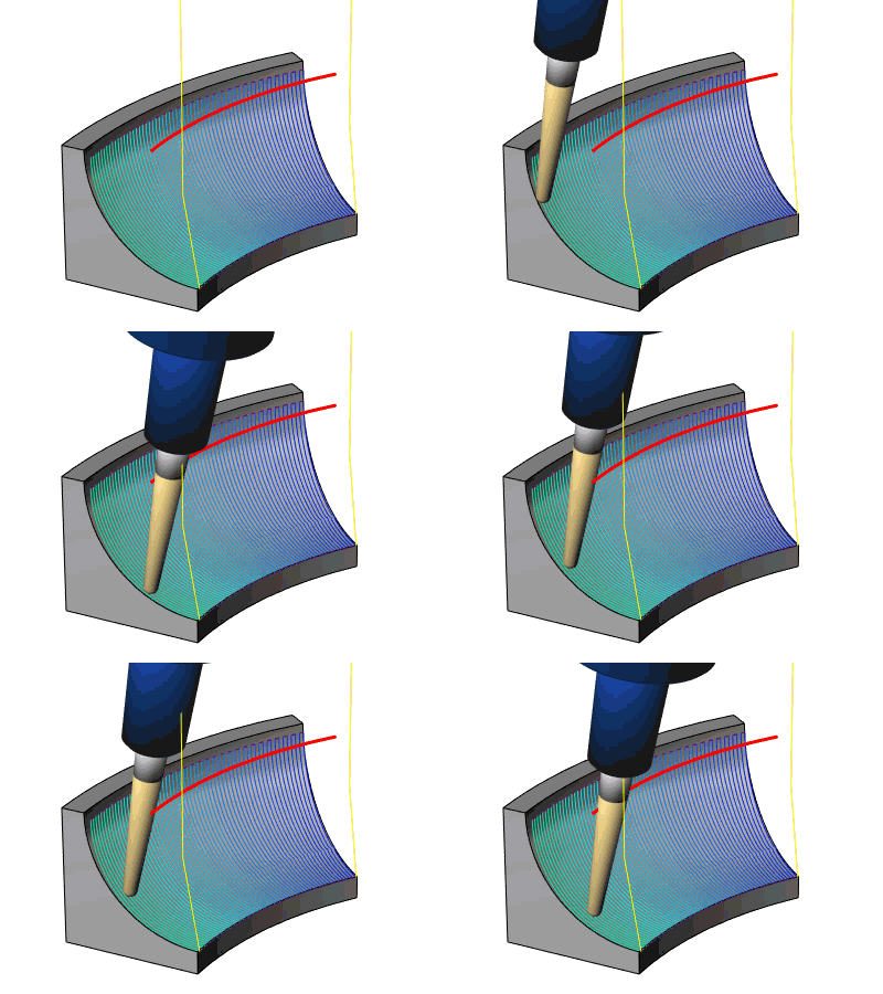
![]() Click here to see Common Direction
in use.
Click here to see Common Direction
in use.
![]() On all contours - will
run the entire drive surface using the same common direction.
On all contours - will
run the entire drive surface using the same common direction.
![]() On single contours - will
set the tool tilt to the average normal direction for each individual
pass.
On single contours - will
set the tool tilt to the average normal direction for each individual
pass.
![]() Clear the check box and Common Direction will not adjust the tilting strategy.
Clear the check box and Common Direction will not adjust the tilting strategy.
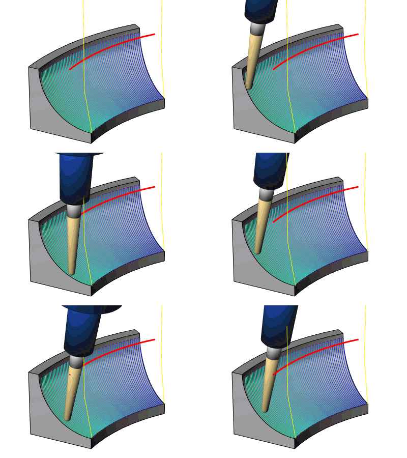
![]() Click here to see default tilting
strategy without Common Direction.
Click here to see default tilting
strategy without Common Direction.
Note: Common Direction is only active when a ball end, or lollipop mill is chosen.
