Mill Turn Clearance Settings
Introduction
This topics explains the clearance options for creating mill or lathe features in a Mill Turn job.
Clearance Settings
When you click the Clearance button in the Machine Setup for a Mill Turn job, the following options display in the Clearance dialog box.
Stock Bounds
Automatically Detect the Stock Bounds
When the Auto check box is selected under Stock Bounds, the software automatically sets the four stock bounds parameter values for you based on the stock geometry that you define in the Stock Wizard and the machining origin that you define in the Machine Setup. You can click to clear the Auto check box to set the stock bounds parameters manually.
Important: The software automatically populates the Stock Bounds parameters in the Clearance dialog box for you based on the stock geometry and the machining origin. It is important that you properly define the machining origin location and orientation (axes directions) first, so that the software can populate the correct values for you in the Clearance dialog box.
Stock Bounds Parameters
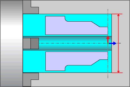
 Stock Diameter
- sets the outside diameter of the stock.
Stock Diameter
- sets the outside diameter of the stock.
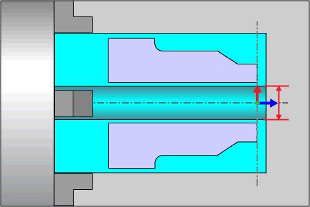
- Internal Diameter
- sets the inside diameter of the stock.
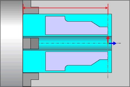
- Face Z
- defines the Z-axis value for the front face of the stock (from the
machining origin).
- End of Stock Z
- defines the Z-axis value for the back face of the stock (from the
machining origin).
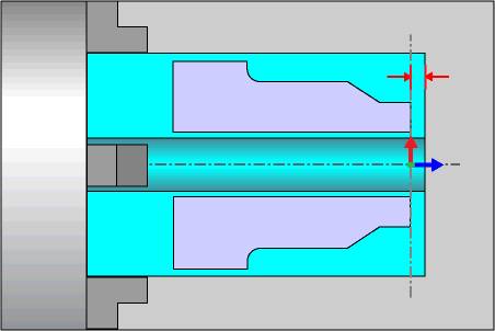
Clearance
- Face -
sets the amount of clearance that is applied (in Z) for rapid movements
along the stock face.
- Diameter
- sets the amount of clearance applied (in X) for rapid movements
along the outside diameter of the stock.
- Internal Diameter
- sets the amount of clearance applied (in X) for rapid movements
along the inside diameter of the stock.
Material Approach Settings (Mill Features)
This section explains the Clearance settings that display under Material Approach in the Feature page of the milling wizards. These values are available when defining milling features in a Mill Turn job.
-
Clearance - defines the safe rapid plane used between machining operations. Click the down arrow to select one of the following options that determine what clearance is used for all operations in the feature:
-
Auto - the software automatically sets the clearance movement for each operation based on the tool orientation.
-
Front Face - uses the defined Face clearance for all operations.
-
OD - uses the defined Diameter clearance for all operations.
-
ID - uses the defined Internal Diameter clearance for all operations.
-
Back Face - uses the defined Face clearance for all operations.
-
None - no clearance plane values are applied to the operations. The rapid plane is used between operations instead of the clearance.
-
Rapid Plane - is the height at which the tool can rapid safely within a single machining operation. This value is incremental from the Top of Feature setting in the CAM wizard.
-
Feed Plane - is the height at which the tool movement changes from rapid to feedrate. This value is incremental from the toolpath.
To learn about all other parameters on the Feature page of the milling wizards, access the appropriate topics through the Milling Features Overview topic.