Cutsim
Introduction
This topic will explain the CutSim tab, and the items found in it. This topic will also provide links to related topics.
The CutSim Tab
The CutSim tab provides parameters for the material removal. This tab contains buttons for saving the stock model (current or at each tool change), creating a sectional view of the stock model, and the Advanced Properties dialog box.
Options
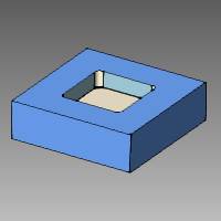
Save Stock
![]() The resulting stock
model can be saved to an .stl file (during or after the machining). When
you click this button, the Save As dialog box displays for you to name
and select a location to save the .stl file of the current stock model
in simulation. Note that further stock saving options can be accessed
using the Advanced Properties dialog box explained next.
The resulting stock
model can be saved to an .stl file (during or after the machining). When
you click this button, the Save As dialog box displays for you to name
and select a location to save the .stl file of the current stock model
in simulation. Note that further stock saving options can be accessed
using the Advanced Properties dialog box explained next.
Advanced Properties
![]() When you click this
button, the Advanced Properties dialog box displays with various options
for saving stock models, gouge and excess settings, and a sectional view.
When you click this
button, the Advanced Properties dialog box displays with various options
for saving stock models, gouge and excess settings, and a sectional view.
Save Results (Save stock model to .stl file)
The Save Stock Geometry at Each Tool
Change check box can be selected to have the system automatically
save an .stl file of the stock model at each tool change during simulation.
You can type the entire file path and name into the box or click the ![]() button to open the Save
As dialog box and specify the name and location to which the files are
saved. While running simulation, the files are automatically saved to
the selected location with the file number appended to the name (Name0.stl,
Name1.stl, Name2.stl etc.).
button to open the Save
As dialog box and specify the name and location to which the files are
saved. While running simulation, the files are automatically saved to
the selected location with the file number appended to the name (Name0.stl,
Name1.stl, Name2.stl etc.).
Gouge and Excess Settings
You can also specify Gouge and Excess Settings that are used when simulating a program as follows.
Offset to Target Part
This specifies the allowance to the target geometry for gouge and excess reporting.
Relative Threshold for Gouge and Excess Report
This value specifies the threshold for gouge and excess reporting.
Show Gouge and Excess Information for Uncut Material
This option allows you to include uncut material in the gouge and excess reporting.
Section Plane (Sectional View)
The Section Plane option allows you to specify a plane to create a sectional view of the model in the simulation window.
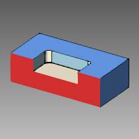
To create a section view after opening Advanced Properties:
-
Click the Enable check box to select it and turn on the section plane.
-
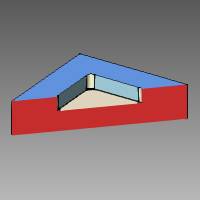
Move the Shift slider to view the current Normal direction for the section view.
This defines the distance between the workpiece coordinate system and the sectional viewing plane (based on the Normal or direction vector). -
Update the Normal direction vector as needed to define the sectional viewing plane.
Note: The Normal direction defines a vector for the sectional viewing plane. With values of X1 Y0 Z0, the plane is parallel to the X-axis. With values of X0 Y1 Z0, the plane is parallel to the Y-axis.
-
Adjust the Shift slider as needed to get the desired sectional view.
-
Click OK.
To turn off the section plane view:
-
Click the Advanced Properties button, and clear the Enable check box in the Parameters dialog box.
Data Model
The data model can be automatic, 3 axis, or 5 axis.
-
Automatic sets the right mode suitable for the simulated part.
-
3-axis model is meant to be used for 3-axis machining in Z without undercuts.
-
5-axis allows undercut material removal.
Accuracy
The accuracy is the resolution of the stock model. A low accuracy brings more speed but a less accurate result. A high accuracy slows the machining simulation down, but the resolution of the stock model is more accurate.
Check
The check option handles whether a part of a tool should remove the material, be gouge checked, do both, or do nothing. This can be set separately for the Flute, Shaft, Arbor, or Holder as explained next.
Flute
- Cut - Only material removal,
no gouge checking.
- Cut and collision check (rapid moves) - Material removal and gouge checking.
Shaft, Arbor, and Holder
- None - No material removal,
no gouge checking.
- Cut - Only material removal,
no gouge checking.
- Cut and collision check - Material removal and gouge checking.
Related Topics
Getting Started With Simulation