Using Compensation
Introduction
This topic will explain compensation in CAM operations, will explain the different compensation options available, will provide an example of compensation, and will provide links to related topics.
Compensation
When target geometry is chosen for a feature we are actually choosing a collection of precise points forming a path. In some cases, we may want the center of the tool to follow that path, but in most cases, the path we choose represents the final surface of our finished product which would be ruined if the center of the tool were to travel along it. This is where our compensation choices come in. With compensation we can specify whether the center of the tool should move along the selected path, or whether the tool should follow an offset path based on the radius of the tool. If the tool is to follow an offset path, should that path be offset to the left of the tool direction, or to the right? For every 2 Axis CAM operation in BobCAD-CAM we decide how to handle this with System Compensation, and Machine Compensation:
- System Compensation
The compensation is handled by BobCAM. The toolpath itself will be offset from the selected geometry, and the output code will follow this toolpath.- Off - The toolpath, and output coordinates, will not be offset.
- Left - The toolpath, and output coordinates, will be offset to the left of the tool direction. The distance of the offset will be equal to the radius of the tool.
- Right - The toolpath, and output coordinates, will be offset to the right of the tool direction. The distance of the offset will be equal to the radius of the tool.
- Off - The toolpath, and output coordinates, will not be offset.
- Machine Compensation
The compensation is handled at the machine controller. BobCAM will output the codes for cutter compensation specified in the post, and the desired offset can be entered at the controller. The toolpath itself, and the coordinates of the output path, will not be affected by this compensation option.- Off - No compensation calls will be added to the output code.
- Comp Left / G41 - The code specified as Cutter compensation left code in the post processor will be output. The distance of the offset will be handled at the machine controller.
- Comp Right / G42 - The code specified as Cutter compensation right code in the post processor will be output. The distance of the offset will be handled at the machine controller.
- Off - No compensation calls will be added to the output code.
Climb cutting vs Conventional cutting
Understanding the difference between these cutting methods is an important first step in their implementation.
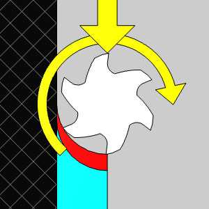
- Climb cutting
This method is sometimes referred to as "Down cutting". The reason for this is evident in the following image.
|
|
Notice how the next tooth will move down into the material, and how the chip will end much smaller than it starts.
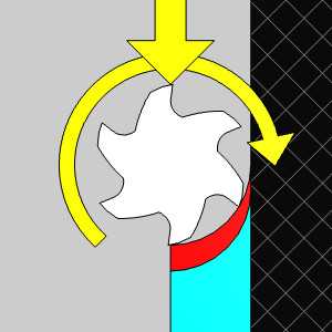
- Conventional cutting
This method is sometimes referred to as "Up cutting". The reason for this is evident in the following image.
|
|
Notice how the next tooth will push up into the material, and how the chip will end much larger than it starts.
Chain direction: Clockwise or Counter Clockwise
In this section, we will look at direction of the tool and the compensation needed to achieve climb and conventional cuts.
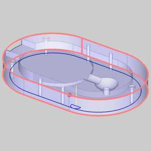
Stock: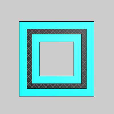
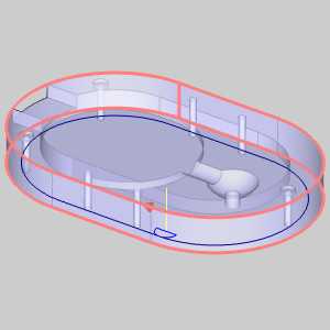
Climb cuts:
To achieve a Climb cut on an inside geometry, a counter clockwise direction used with left compensation is necessary.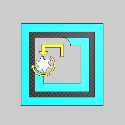
To achieve a Climb cut on an outside geometry, a clockwise direction used with left compensation is necessary.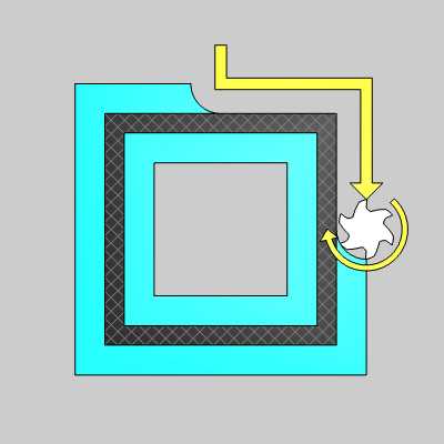
In the image below you can see how inner and outer climb cuts require opposing directions. 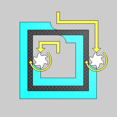
Conventional cuts:
To achieve a Conventional cut on an inside geometry, a clockwise direction used with right compensation is necessary.
To achieve a Conventional cut on an outside geometry, a counter clockwise direction used with right compensation is necessary.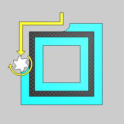
In the image below you can see how inner and outer conventional cuts require opposing directions. 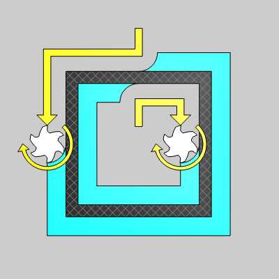
Navigation
To access the compensation options:
- In the Wizards, move to the Patterns page of the individual operations. These options can be set in the Compensation group.
Troubleshooting
The leading confusion from users just getting started with BobCAD-CAM comes into play when toolpath is computed, but it is on the wrong side of their geometry. As we learned in the above examples, this has to do with the direction of the chain versus left or right compensation. For this troubleshooting example, we will use an outside profile cut. If the cut is on the wrong side, check the chain direction; it can only be one of two things:
- Clockwise direction with Right Compensation:
- Looking for a climb cut?
Change the System and/or Machine Compensation to Left.
- Looking for a conventional cut?
Change the chain direction to counter clockwise.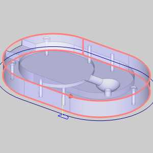
- Looking for a climb cut?
- Counter Clockwise direction with Left Compensation:
- Looking for a climb cut?
Change the chain direction to clockwise. - Looking for a conventional cut?
Change the System and/or Machine Compensation to Right.
- Looking for a climb cut?
Examples
Related Topic
Geometry Selection and Selection Mode for CAM Features