Mill Multiaxis Drilling Example
Introduction
This topic provides an example of how to create multiaxis hole drilling features for milling jobs in BobCAM.
Example File
The part file for this tutorial is available for download at: http://bobcad.com/helpfiles. If you are connected to the Internet, you can click the link provided to download and save the Mill Multiaxis Drilling Example 1 SLDPRT.zip file. After extracting the zip file, you can open the file to follow along with this example. In the example file provided, the job, stock, and machine setup are already defined.
Create a Multiaxis Hole Feature
Set the Drilling Type and Select Geometry
-
In the CAM Tree, right-click Machine Setup and click Mill Drill Hole.
-
In the Mill Hole Wizard, click Select Geometry.
The Hole Geometry Selection Manager displays. -
Before selecting geometry, we need to set the drilling type to multiaxis.
Next to Standard Drill, click the down arrow, and click Multiaxis Drill.
Important: It is important to properly set the drilling type. The drilling type determines what options display in the Selection Manager and how the software filters the geometry selections (when you confirm them).
-
For this example, we select cylindrical surfaces so the software can automatically set the diameter, top of feature, and feature depth from our selections. To learn about selecting other geometry types, view the Point and Arc Usage Example.
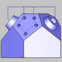
You can select the cylindrical surfaces directly, or you can select features from the Feature Manager Design Tree. For this example, we use the Select Whole Bodies option and allow the software to automatically detect all drill holes in the model for us.
Under Geometry, click the Select Whole Bodies check box and select the model in the graphics area.


Notice the drilling direction indicators that display after selecting geometry. It is important to properly set the drilling direction for multiaxis holes to point to the bottom of the hole.
Important: The software
uses the center of the selected geometry to determine the drilling direction
for multiaxis holes. For many holes this works well, but sometimes it
does not provide the proper direction. Be sure to confirm the proper direction
for each hole (the arrow points to the bottom of the hole).
If you need to reverse the direction, select
one or more entities in the Holes list (the direction indicator highlights
in the graphics area), and click Reverse. (Use the Ctrl or Shift keys
to select more than one item in the Geometry list.)
After checking the direction indicators, we can see that the automatically defined direction is correct for all holes, but there is one hole that we want to remove from our feature.

In the Holes list, click Hole-4 to select it. The drilling direction indicator highlights in the graphics area.

Click Delete to remove only the selected hole from the list.
The drilling direction indicator no longer displays showing that the hole is removed. (Note that the holes in the Holes list are renamed after deleting a hole, so there is still a hole named Hole-4 in the list, which was previously Hole-5.)

-
Click
 to confirm and finish the selection.
 -
In the hole list, click in the first row to select the 0.7500 diameter hole size, and click to clear the Through Hole check box.
Select the 0.3125 diameter hole, and confirm the Through Hole check box is cleared for this hole size. -
Click Next>>.
Define the Feature Settings
After selecting geometry, the software automatically creates hole groups. A hole group is one or more holes that share the same diameter, top of feature, and feature depth. For multiaxis drilling, hole groups must also share the same tool vector (tool orientation). Notice in the wizard tree there are two features. A single feature can contain only one hole diameter, but hole groups allow more than one hole depth in a single feature.
-
For now, we use the default Material Approach settings. The Diameter, Machining Order, and Hole Type are already properly set.
Notice the Apply Material Approach to All button on the lower left. You can use this to apply the Material Approach settings to all features, when there is more than one in the tree.
Next we confirm the hole groups and parameters using the Hole Groups table and preview.
-
Under Hole Groups, click the name Group 1.
Notice that the group is now selected (displays in dark blue), and the name becomes available for editing. (We use the default group name for this example, but making custom group names can greatly help you keep organized when there are many hole groups.)
Tip: To change a group name, top of feature, or feature depth, you click the value in the Hole Groups list to make it available for editing. Generally, you select one or more groups before clicking Break Hole Group, Regroup Holes, Pick Top, or Pick Bottom. To select more than one item, press and hold the Ctrl or Shift key for the next selection.
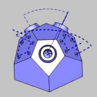
When you select a group, the hole groups preview displays directly inside the Mill Hole Wizard so we can see with which hole we are working.

Note that you may not have the exact same preview as shown in the images.
-
Click anywhere in the row of Group 2 to select it and display the preview.

-
Select Group 3.

What is important to notice here is that all three hole groups for this feature have the same top of feature and feature depth, but they are in separate hole groups. This is because each one of these holes has a different tool vector (tool orientation), and multiaxis hole groups must also share the same tool vector.
Because we selected cylindrical surfaces, the parameters for our hole groups are already properly defined so no changes are needed. To learn about breaking and regrouping holes, view the Break and Regroup Holes Example.
-
Click Next>>.
Define the Machining Strategy
-
Under Template, click Hole.
Selecting this operation template adds one Center Drill and one Drill operation to the Current Operations list. -
On the lower left of the dialog box, click Apply to All Features.
This assigns the same operation template to the Machining Strategy of the second feature. -
Click Next>>.
For this example, we don't make any changes to the Posting or Multiaxis Posting settings.
Define the Tool Data and Operation Parameters
-
In the tree under the first Center Drill operation, click
 Center Drill.
We use the automatically selected System Tool information for this example. When creating your own programs, be sure to properly set all of the information in this page as needed for the job. -
Click Next>>.
We use the default Center Drill Parameters, but notice there are no hole groups listed on this page. The Center Drill Parameters apply to all hole groups in the feature. -
Click Next>>. Again, the System Tool option is used to automatically assign our drill tool information for this example.
-
Click Next>>.
-
Under Hole Groups, Click Group 1 to select it.
Under Cycle Type, click Peck.
Always make sure to select a hole group before changing settings in the Parameters page. -
Click Group 2, and then select Peck.
Set Group 3 to Peck using the same process.
Important: Be sure to select a hole group before changing any operation parameters, and make sure to set the parameters as needed for all hole groups.
-
Click Next>>.
Define the Second Feature and Compute the Toolpath
As with the first feature, the feature settings are already correct, but let's confirm the hole groups that were created for this example file.
-
Under Hole Groups, click anywhere in the row of Group 1 to select it and display the hole groups preview.
Note that your preview may or may not show the same set of holes, depending on the order in which they are selected.

Tip: To change the viewing orientation of the preview, drag the left or middle mouse button to rotate. To pan the preview, press and hold the Ctrl key, and drag the middle mouse button. To zoom in or out, roll the middle mouse button forward or backward.
-
Select Group 2.

-
Notice that each group has the same top of feature and feature depth, but we end up with two groups because each group has a different tool vector.
Tip: For Multiaxis Hole features, the Top of Feature is in reference to the selected geometry (and drilling direction), not the machining origin. So, generally, the Top of Feature is set to 0.000 for multiaxis hole features. You should only need to change it from 0.000 when the geometry you select is above or below the actual hole location.
-
Click Next>>.
-
The Machining Strategy is already set from using Apply to All Features earlier.
No other changes are needed for this example. -
On the lower right, click Compute.
The toolpath result is shown next.

Notice in the second image that our group retracts (rapid movement between hole groups) are set to a plane above the part. While this setting works fine for our example part, it is often beneficial to use a spherical retract area for multiaxis machining. In the next part of this example, we learn how to edit our features and create a spherical retract area.
Edit the Features and Define Spherical Group Retracts
It is important to understand how rapid movement is applied to hole groups. The rapid plane value determines the safe rapid distance within a single hole group. The rapid movement between hole groups is determined by the group retracts. The group retracts provide advanced options for defining planar, cylindrical, or spherical retract areas.
-
In the CAM Tree, right-click the first feature name, Multiaxis Feature Mill Hole - 0.7500, and click Edit.
-
Under Material Approach, click Group Retracts.
-
Next to Type, click the down arrow, and select Sphere.
Change the Radius value to 4.000.
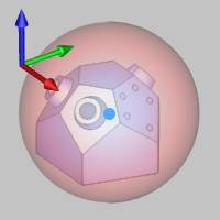
Setting the Base Point parameters properly is an important part of defining a spherical clearance area. The Base Point XYZ values are in reference to the machining origin, which is currently set to the top corner of a rectangular stock from which the part is cut. (Note that the stock in the file is the same as the model, not rectangular as shown in this image, but our machining origin is in the same location.)

If needed, you may want to create a sphere primitive to help you visualize the spherical clearance area and confirm the proper settings.

-
Under Base Point, set the following values:
-
X = 2.8530
-
Y = 2.7140
-
Z = -2.0000
These values determine the distance from the machining origin to the base point (center) of the sphere.
-
Click OK.
-
Click Compute.

After making the same changes to the second feature, the toolpath is as follows.

Notice that changing the group retracts does not change the rapid movement within the groups on either side of the model. It only changes the rapid movement (links) between the hole groups.
This concludes the example.