How to Create a Multiaxis Roughing Feature
Introduction
This tutorial explains how to create a Multiaxis Rouging Feature. Multiaxis Roughing always uses the surface normal direction of the part to define the tool axis orientation. The example explains proper geometry selection based on the roughing strategy used. An important note about selecting floor surfaces for multiple-pocket parts is also explained.
Example File
The SolidWorks part file for this tutorial is available for download at: http://www.bobcad.com/helpfiles. If you are connected to the Internet, you can click the link provided to download and save the Multiaxis Roughing Example 1.SLDPRT zip file. After extracting the zip file, you can then open the example file to use with this tutorial. In the example file provided, the stock and Machine Setup are already defined for the part. The part is simulated using the BC Table Table machine.

Part 1) Add the Feature
-
 CAM Tree tab.
-
Right-click
 Machine
Setup and click Mill Multiaxis.
Machine
Setup and click Mill Multiaxis. -
In the Multiaxis Wizard, click Multiaxis Machining.
-
Click Next>> to go to the Posting dialog box.
Part 2) Define the Posting Parameters
-
The Work Offset # is automatically set to the value defined in the Machine Setup dialog box.
You can change the value here to update the Work Offset # for the feature. -
Click Next>> to go to the Multiaxis Posting dialog box.
Part 3) Define the Multiaxis Posting Parameters
-
Notice, at the top of the dialog box, that the Use Machine Settings check box is selected.
This means that the Multiaxis Posting parameters for the feature use the same parameters as the machine that is selected in Current Settings.
You can clear the Use Machine Settings check box to define the Multiaxis Posting parameters of the feature separately from the current machine settings.
For this example, no changes are needed.
-
Click Next>> to go to the Tool page.
Part 4) Define the Tool Parameters
-
In the Tool Data group, set the Diameter to 0.750, and set the Corner Radius to 0.00.
Clear the System
Tool check box.
System
Tool check box.
Set the Flute Length to 3.00, and set the Overall Length to 5.00.
Depending on your Tool Library, the 0.75 tool holder may already be assigned. If it is already assigned, skip Step 2. -
To assign a holder, click Assign Tool Holder.
In the Milling Tool Holder Library dialog box, with CAT 40 Holder selected, click 0.75 inch I.D. Arbor CAT 40.
At the bottom of the dialog box, click OK. -
Click Next>> to go to the Parameters dialog box.
Part 5) Define the Cut Pattern
-
To create a toolpath of parallel cuts that is offset from the floor surface: in the Pattern group, next to Pattern, select Offset From Floor.
For this example, the default Type, Offset, is used. If you want to make the Multiaxis Roughing operation a high-speed machining operation, change the type to Adaptive. The Adaptive pattern automatically creates the high-speed machining without any other settings required. Be aware that some available feature parameters change slightly depending on the selected pattern Type. -
In the Sorting group, set the Cutting Method, to Zigzag.
-
In the Stepover group, set the Maximum Stepover amount to 0.375.
-
To define the depth of cut, in the Constant Depth Step box, type 0.500.
This value is the maximum depth of cut and the system automatically creates the number of passes necessary to machine the part.
Part 6) Select Geometry
-
Click the Part Definition tab.
-
In the Part Definition group, next to Part Surfaces, click
 .
.
In the Feature
Manager design tree, click the Part
Model feature.
Feature
Manager design tree, click the Part
Model feature.
-
In the Part Definition group, next to Floor Surfaces, click
.
In the graphics area, select the floor surface as shown next.
This defines the area to which the toolpath is applied as well as the bottom of the part.
-
To accept the selection, click
 OK.
OK. -
Next to Part Surfaces, in the Stock to Leave box, type 0.015.
-
Next to Floor Surfaces, in the Stock to Leave box, type 0.030.
This leaves material remaining for a finishing operation on the wall and floor surfaces. -
At the top of the dialog box, click Roughing.
Confirm that the Stock Definition check box
is selected.
Stock Definition check box
is selected.
If the check box is not selected, no toolpath is created. -
To create the toolpath, at the bottom of the Multiaxis Wizard, click Compute.

The following image shows the part after simulation.
(To view the program, in the Simulation.)

Part 7) More About Cut Pattern
When using the strategy Offset From Floor, you do not need to define a ceiling surface. For the other two strategies, Offset From Ceiling and Morph Between Ceiling and Floor, you must define a Ceiling Surface. The ceiling surface must span the entire area of the part, and is often the top surface of the stock geometry.
-
To define a ceiling surface, in the CAM Tree, right-click Ceiling Surface, and click Re/Select.
(You may need to expand the Geometry folder of the Multiaxis feature.)
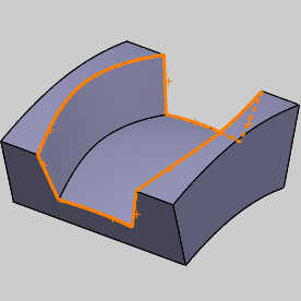
In the graphics area, select the ceiling geometry as shown next.
While the ceiling in the image above will suffice for this part, in some cases you should select as much as possible or even create an untrimmed ceiling to use as in the images below.

-
To confirm the selection, click
OK. -
When you computed the toolpath, the
 Multiaxis
feature was added to the
CAM Tree.
Multiaxis
feature was added to the
CAM Tree.
To edit the feature, in the CAM Tree, right-click FeatureMultiaxis, and click Edit. -
Click Parameters.
In the Surface Paths tab, in the Pattern group, select the Strategy. -
If you select the Strategy Offset From Ceiling, the toolpath cuts are created parallel to the ceiling surface.
-
If you select the Strategy Morph Between Ceiling and Floor, the feature creates an offset from the ceiling and an offset from the floor and blends (morphs) the two paths together to create the toolpath.
Part 8) Using 3D Boundaries
In the Surface Paths tab of the Multiaxis wizard, the 3D Containment allows you to limit the Multiaxis Roughing operation using 3 dimensional containment curve. The following is a quick example usage.
The part in this example is an open pocket, which allows the toolpath to continue past the bounds of the part. Let's imagine that this is not the desired result, but you don't want to create new geometry to create a closed pocket. You can select the edges directly from the model to contain the toolpath within the bounds of the part.
For visual reference, the following image shows the original toolpath created in this example.
-
In the Area group of the Surface Paths tab, select the 3D Containment check box.
-
Click 3D Containment and select the 3D containment curves from wireframe geometry or directly from the model edges.
To confirm the selection and return to the
wizard, click ![]() OK.
OK.
-
Click Compute.
The toolpath is now contained within the selected 3D boundary.

This concludes the example.