Multiaxis Machining
Introduction
The Multiaxis Roughing operation is used to rough large amounts of material with multiaxis movements. The tool tilting is defined using the surface normal direction of the part geometry. This feature type requires multiple surface selections depending on the selected pattern. This topic explains the Multiaxis Wizard parameters that are available when using the Multiaxis Roughing feature type.

Surface Paths
Pattern
- Machining
- select from one of the following operations.
- Roughing - Removes the bulk of the material with multiaxis moves.
- Floor Finishing - Finishes the floor surfaces with multiaxis moves.
- Wall Finishing - Finishing the wall surfaces with multiaxis moves.
- Roughing - Removes the bulk of the material with multiaxis moves.
- Pattern
- select from one of the following strategies.
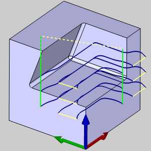
- Offset
From Floor - When using the Roughing, this option creates parallel cuts that are offset from
the selected Floor Surface.
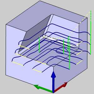
- Offset
From Ceiling - When using the Roughing, this option creates parallel cuts that are offset from
the selected Ceiling Surface.
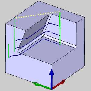
- Morph
Between Ceiling and Floor - When using the Roughing or Wall finishing, this option creates cuts that morph or
blend between the Ceiling and Floor Surfaces.(The Ceiling Surface
button becomes available on the Part Definition tab when this
option is selected.)
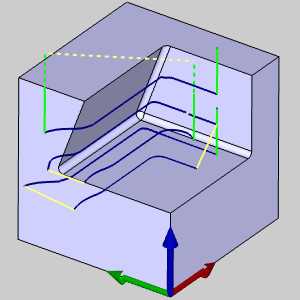
- Offset from wall - When using the Floor finishing, this option creates an offset of the wall to apply the finish to the floor.
- Offset
From Floor - When using the Roughing, this option creates parallel cuts that are offset from
the selected Floor Surface.
- Type
- Offset - When using the Roughing, this option creates a standard offset pattern
from the selected geometry.
- Adaptive - When using the Roughing, this option creates the feature using the
Adaptive high-speed machining strategy. The constant tool engagement
is automatically calculated for the feature.
- Offset - When using the Roughing, this option creates a standard offset pattern
from the selected geometry.
- Guide curve - When using the Floor finishing with a Parallel pattern, this option becomes available.
- Longest dimension - When using the Floor finishing option, this will identify and utilize the longest edge of the floor in order to create a parallel pattern from.
- Floor curve - will utilize the edge of the floor in order to create a parallel pattern from.
- Ceiling curve - When using the Wall finishing option, this will utilize the edge of the floor in order to create a parallel pattern from.
- User defined drive - this option will allow you to select custom geometry to use as a guide curve.
- Longest dimension - When using the Floor finishing option, this will identify and utilize the longest edge of the floor in order to create a parallel pattern from.
Sorting
-
Cutting Method
-
Zigzag - creates a toolpath with an alternating cutting direction.
-
One Way - creates a toolpath that only cuts in one direction. A retract and rapid move is created at the end of each toolpath slice.
-
Direction For One Way Machining - when using the One Way cutting method, set the cutting direction to Climb or Conventional.
-
Machine By - select one of the following options to define the machining order.
-
Levels - cuts the entire part to one depth before moving on to the next depth.
-
Regions - cuts each region of the part to the total depth before moving on to the next region.
-
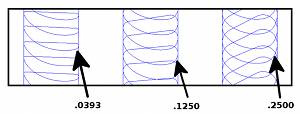
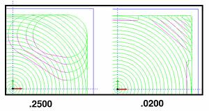
Stepover
The parameters used to define the stepover change slightly depending on the selected pattern settings.
With Offset
-
Maximum Stepover - is the not-to-exceed distance between each toolpath slice.
-
Cusp Height - is used to define the stepover value using a cusp height instead of a distance when using a ball endmill.
With Adaptive and One Way
-
Maximum Stepover - is the not-to-exceed distance between each toolpath slice.
-
Desired Stepover - is the optimal stepover for the feature which is used as much as possible.
With Adaptive
and Zig Zag
-
Climb Stepover (% Stepover) - is the percentage of the Stepover value that is applied to climb cutting passes.
-
Conventional Stepover (% Stepover) - is the percentage of the Stepover value that is applied to conventional cutting passes.
Depth Step
To define the depth steps of the feature, select one of the following two options.
-
Constant Depth Step - determines the maximum amount of material removed for each pass. Type the positive value that you want to use for each depth step. The software automatically calculates the appropriate number of steps.
-
Number of Slices - type a number of slices (or passes) to define the depth of cut for the feature. The software automatically calculates the depth steps value.
-
Advanced - opens the Depth Step dialog box for you to further define the depth step with advanced options as follows.
-
First Depth Step
 Select the check box to define a cutting
depth for the first cut depth only. Type the value that you want to apply
to the first depth step.
Select the check box to define a cutting
depth for the first cut depth only. Type the value that you want to apply
to the first depth step. Clear the check box when the first
cut is the same as all other cuts.
Clear the check box when the first
cut is the same as all other cuts. -
Final Depth Step
Select the check box to define a cutting
depth for the last cut depth only. Type the value that you want to apply
to the last depth step.Clear the check box when the final
cut is the same as all other cuts. -
Value
Select the check box to type specific values at which the depth steps
are created. When you select this option, a table displays for you to
add values (Z-axis). Right-click anywhere in the table to access a shortcut
menu for adding or removing items. After adding an item, set the desired
value for it.
Clear the check box to turn off the value depth step option. -
Intermediate Slices
Select the check box to define intermediate
slices using one of two options. Clear the check box when not using intermediate
slices.-
Constant Depth Step - automatically creates intermediate slices based on a value (depth) you define. Type the depth step value applied to create a stepped machining in any area with rest material.
-
Number of Slices - automatically creates intermediate slices based on a number of slices you define. Type the number of slices to use in the box to create stepped machining passes in area with rest material.
-
Area
After creating a roughing operation, you can create a second operation with Rest Roughing that uses a smaller tool than the first roughing operation. The system automatically finds and applies the toolpath only to the areas not machined by the previous tool.
- Rest Rough
Select the check box to turn on the rest-roughing option. To open the
Rest Roughing dialog box and define the parameters, click Rest Rough.
Clear the check box to turn off rest roughing.- Roughing Tool Diameter - type the diameter of the previously used roughing tool.
- Roughing Tool Corner Radius - type the corner radius of the previously used roughing tool.
- Roughing
Offset - type the offset value of the previously defined
roughing operation.
- 3D Containment
Select the check box to turn on 3D containment which allows you to assign
a 3-dimensional curve to define the boundary for the operation. Click
3D Containment, select the geometry from wireframe or surface edges, and
confirm the selection to return to the wizard. The resulting toolpath
is contained within the boundary, but be aware that the current stock
definition may cause cutting outside of (above) the boundary if there
is stock to be removed.
Clear the check box to turn off 3D Containment.


- Undercuts - dictates if undercutting is handled. Choose between:
- Do not machine - will prevent undercut areas from being handled in the toolpath.

- Machine - will include undercut areas in the toolpath.

- Machine only - will only handle the undercut area and exclude all other toolpath.

- Do not machine - will prevent undercut areas from being handled in the toolpath.
- Extend undercuts - allows you to define an extra area to be handled, beyond the undercut itself, when the Machine only option is used.
| Machine only | Machine only with extension |
|
|
Part Definition
Part Definition
-
Floor Surfaces - click
 to enable selection mode and select the floor surface.
 -
Stock to Leave - is the amount of material that remains on the surface (for finishing).
-
Wall Surfaces - click
to enable selection mode and select the wall surfaces. This should
be the entire part, but do not include a ceiling surface.-
Stock to Leave - is the amount of material that remains on the surface (for finishing).
-
-
Ceiling Surfaces - only used with the strategies (Surface Paths page): Offset From Ceiling and Morph Between Ceiling and Floor. Click
to enable selection mode
and select the ceiling surface.
Surface Quality
-
Cut Tolerance - type a value to define how accurate the toolpath is in relation to the selected geometry. Smaller values create a more accurate toolpath but also increase calculation times.
Tip: You can reduce the cut tolerance value, for example from 0.0005 to 0.005, to speed up the toolpath calculation while creating and modifying your toolpath. Once your are happy with the result, you can then set it back to the original tolerance to calculate the toolpath before posting the output.
Gouge check
To learn about the Gouge check parameters, view the Multiaxis Gouge Checking. The Multiaxis Gouge checking options are limited to the options available in the dialog box.
Link
To learn about the Link parameters, view the Multiaxis Links. The Multiaxis Roughing Links are limited to the options available in the dialog box.
Roughing
Stock Definition
The Multiaxis Roughing feature requires that the following check box is selected in order to create a toolpath.
-
Stock Definition
![]() Select the check box to enable the Multiaxis Stock Definition parameters.
Click Stock Definition to open the Stock Definition dialog box.
Select the check box to enable the Multiaxis Stock Definition parameters.
Click Stock Definition to open the Stock Definition dialog box.
![]() If you clear the check box no toolpath is created.
If you clear the check box no toolpath is created.
Stock Definition Parameters
-
Tolerance - defines the allowance from the defined stock. Smaller values are more accurate and may increase the toolpath calculation time.
-
Shrink - select this option and type a value used to shrink the defined stock geometry.
-
Expand - select this option and type a value used to expand the defined stock geometry.
Note: The Shrink and Expand values offset the stock geometry in all three directions.
Advanced
Advanced - opens the Advanced dialog box with the following parameters. The Smoothing parameters explained next are only available when using the Offset pattern, not the Adaptive pattern.
Smoothing
The following options display in the Smoothing group when the Type (Surface Paths tab) is set to Offset.
- Smooth Corners
Select the check box to create fillets in the sharp corners
of the toolpath. The fillet is not applied to the outer contour as it
is with Smooth Final Contour. When selected, the Smooth Distance/Stepover
% parameter becomes available as well as the Smooth Final Contour option.
Clear the check box to turn off Smooth Corners.- Smooth Distance/Stepover
% - sets the
radius of the fillet as a percentage of the stepover distance.
- Smooth Distance/Stepover
% - sets the
radius of the fillet as a percentage of the stepover distance.
- Smooth Links
Select the check box to smooth the links within a group. The last segments
of the previous contour and the first segments of the next contour are
trimmed. The connecting link connects diagonally. In the case of a Blend
Spline the connection is an S-type link.
Clear the check box to turn off Smooth Links.- Smooth
Link Gap Size - determines the distance over which
the smooth s-links are applied to link two toolpath slices.
- Smooth
Link Gap Size - determines the distance over which
the smooth s-links are applied to link two toolpath slices.
- Smooth Final Contour
Select the check box to create fillets in the sharp corners of outer contours.
The Smooth Distance/Stepover % parameter becomes available.
Clear the check box to turn of Smooth
Final Contour.- Smooth Distance/Stepover
% - sets the radius of
the fillet as a percentage of the stepover distance.
- Smooth Distance/Stepover
% - sets the radius of
the fillet as a percentage of the stepover distance.
-
Minimal Curvature Radius - determines the smallest radius used in the toolpath motion. This value must be greater than zero, but be aware that if you set this value too high, no toolpath is created. This parameter is useful, for example, to determine how far into a corner the toolpath can reach.
Note: The Minimal Curvature Radius option is the only one available in the Smoothing group when the Type (Surface Paths tab) is set to Adaptive.
Filtering
- Type - allows you to remove toolpath regions based on their size. If the width of a toolpath region is less than or equal to the specified threshold, this region will be filtered out. Choose between:
- Inscribed circle - the width of the region is a maximum circle diameter, which could be inscribed into the toolpath within this region.
- Diagonal length - the width of the region is a diagonal of the axis-aligned bounding box built around the toolpath within this region.
- Inscribed circle - the width of the region is a maximum circle diameter, which could be inscribed into the toolpath within this region.
- Threshold Value in % of Tool Diameter - sets the size of small toolpath segments to remove as a percentage of the tool diameter.
-
Remove Corner Pegs
![]() Select the check box to have the software created toolpath to remove corner
pegs or stand ups left at the edges of the feature.
Select the check box to have the software created toolpath to remove corner
pegs or stand ups left at the edges of the feature.
![]() Clear the check box to turn off Remove Corner Pegs.
Clear the check box to turn off Remove Corner Pegs.
- Extend cuts for stock
With this option selected, the toolpath is extend to cut stock that exists above the selected ceiling. With this option cleared, the toolpath will end at the selected ceiling.
Note: The Extend cuts for stock option is only available when the Morph between floor and ceiling option is used in the Pattern group of the Surface Paths tab.
Approach Moves
- Ramp Type - sets the lead-in motion for the rough toolpath segments (for center cutting tool only). Several ramping strategies are available:
- Automatic - automatically selects from the following ramp options: Line, Spiral, Zig Zag, and Profile are attempted in this order until a ramp entry that does not gouge is accomplished.
- Max ramp length (tool diameter %) - sets the maximum length of a single ramp move. The value entered here is a percentage of the tool diameter being used.
- Min ramp length (tool diameter %) - Selecting this check box allows you to specify a minimum length to use for the ramp. The vale entered here is a percentage of the tool diameter being used.
- Max ramp length (tool diameter %) - sets the maximum length of a single ramp move. The value entered here is a percentage of the tool diameter being used.
- Line - the lead-in move is along an angular line, using the Ramp Angle value.
- Helical - creates a helical or spiral entry into the stock material, the tool engages the stock with helical interpolation. The Ramp Length and Angle of Approach value define the helix.
- Max ramp length (tool diameter %) - sets the maximum length of a single ramp move. The value entered here is a percentage of the tool diameter being used.
- Min ramp length (tool diameter %) - Selecting this check box allows you to specify a minimum length to use for the ramp. The vale entered here is a percentage of the tool diameter being used.
- Max ramp length (tool diameter %) - sets the maximum length of a single ramp move. The value entered here is a percentage of the tool diameter being used.
- Zig Zag - similar to line ramp, the length of the ramp is limited so you get zig and zag angular moves. The zag move is in opposite direction to the zig move and at the same angle to the horizontal. This uses the Angle of Approach and Ramp Length values. This option is only available when the Offset Pattern Type is selected in the Surface paths tab.
- Max ramp length (tool diameter %) - sets the maximum length of a single ramp move. The value entered here is a percentage of the tool diameter being used.
- Min ramp length (tool diameter %) - Selecting this check box allows you to specify a minimum length to use for the ramp. The vale entered here is a percentage of the tool diameter being used.
- Max ramp length (tool diameter %) - sets the maximum length of a single ramp move. The value entered here is a percentage of the tool diameter being used.
- Profile - the tool engages the stock following the contour of the part or the toolpath profile. This option is only available when the Offset Pattern Type is selected in the Surface paths tab.
- Automatic - automatically selects from the following ramp options: Line, Spiral, Zig Zag, and Profile are attempted in this order until a ramp entry that does not gouge is accomplished.
Note: All of the options work similar to the automatic ramp option, that is if that particular option fails, the other ramp options are attempted. IF no ramp strategy is possible in that given area, then a plunge move is applied.
- Ramp angle - defines the angle at which the tool enters the next slice or pass.
- Allow Tool
Outside Stock
Select the check box to allow the tool to travel outside of the defined
stock geometry. For example, when the defined stock is the same as the
part geometry.
Clear the check box to turn off Allow Tool Outside Stock.
- Stock clearance (stepover %) - defines the start point of the ramp with this value as a minimum distance away from the stock. The value is used from a percentage of the stepover value.
Adaptive Links
The following options display in the Roughing tab when the Adaptive pattern type is selected on the Surface Paths tab.
- Link Clearance - is the clearance height applied to create a retract move to link non-connected cuts when using the Adaptive cut pattern (Type). This value can be set to zero to remove the link clearance from the toolpath. The value can't be greater than the depth of cut and when using Intermediate slices, the value can't be greater than the depth of cut divided by one plus the number of intermediate slices. [0 <= Link Clearance < Depth of Cut / (1 + Number of Intermediate Slices)]
Tip: The Maximum Cutting Feedrate (in Current Settings) is applied to the adaptive link moves between cuts.
- Link Length Threshold (X Tool
Diameter) - allows you to define the maximum length of the
(adaptive) link moves before applying a standard retract move in its
place. Link moves less than this value use the Link Clearance value
and link moves greater than this value are replaced with a retract
to clearance. The value is specified as a multiple of the tool diameter,
for example, 2 is twice the tool diameter.
-
Arc Leads
- with this check box cleared, linear leads will be used.
Arc
Leads - with this check box selected,
vertical tangential arc moves will be used as default lead-in/outs. The
radii of generated lead arc segments are determined by the specified entry/exit
feed distances.
Utility
To learn about all of the Utility parameters, view the Utility Tab.
The Utility parameters explained next are only available for the Multiaxis Roughing feature.
Feed Rate Control
- Feed control zone
Select the check box to
turn on the feed control zone option which allows you to specify a
geometric boundary as an area to apply a special feedrate. To define
the parameters in the Feed Control Zone dialog box, after selecting
the check box, click . Clear
the check box to turn off the option.
Feed Control Zone Dialog Box
-
Geometry - click
to
select geometry as the boundary area for feedrate control. -
Offset - type a positive value here to offset the boundary area from the selected geometry thus making the feed control zone smaller.
-
Inside feedrate % - type a percentage of the feedrate that is applied inside of the feed control zone.
-
Outside feedrate - type a percentage of the feedrate that is applied outside of the feed control zone.
- Use rapid
feedrate
Select the check box to use rapid feedrate and type the desired
rapid feedrate value in the box. Clear the check box to turn off rapid feedrate.
Retract moves, for example, now use the standard feedrate.
Feedrate for Direct/Spline Links
-
Area Links
Select the check box to define a feedrate value used for direct or spline
links.
Clear the check box to use the program feed rates. -
Links Between Slice
Select the check box to define a feedrate value used for direct or spline
links.
Clear the check box to use the program feed rates. -
Links Between Regions
Select the check box to define a feedrate value used for direct or spline
links.
Clear the check box to use the program feed rates.
Miscellaneous
Max. Angle Step for Rotation Axis
This option determines the maximum angle step, or amount or rotation, applied to rotation axis movements. Select the check box to turn on the option and then type the angle value in the box.