How to Create a Toolpath Pattern - Points
Introduction
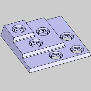
This tutorial explains how to create a toolpath pattern using the Points option. The example provided shows how to pattern multiple features together using a single toolpath pattern with a Group.
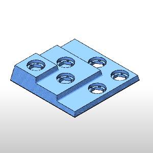
Example Part
The part file for this tutorial is available for download at: http://bobcad.com/helpfiles.
If you are connected to the Internet, you can click the link provided
to download and save the Toolpath Pattern
Points Example 1
Part 1) Blank/Unblank Toolpath
In this example part, we have used a Group to better manage our toolpaths. Adding a toolpath pattern to each of the three toolpaths we intend to duplicate would be a little too time consuming. Adding a toolpath pattern to the entire machine setup, would duplicate toolpaths we have no intention of patterning. The creation of a group, gives us control of all the toolpaths contained in the group at once.
-
In the

-
Right-click the Group in the CAM Tree.
-
Select Blank/Unblank Toolpath.
The toolpath for the three features we intend to pattern is no longer visible in the graphics area.
Part 2) Add the Pattern
With the toolpath hidden, we can now easily pick the points for our pattern.
-
Right-click the Group in the CAM Tree.
-
Select Add Toolpath Pattern.
The Toolpath Pattern dialog appears. -
Select the Points option.
-
Click Next > >.
Part 3) Set the Start for the Toolpath Pattern
With the Toolpath Pattern dialog launched, we are now able to set the
Specified Points. If the distances between the original and its copies
are known, the Start can be left at zero and the differences can be entered.
In this case we will use the Pick options to set the Start and use
the
Important: Pick options reference values in relation to the Machine Setup
-
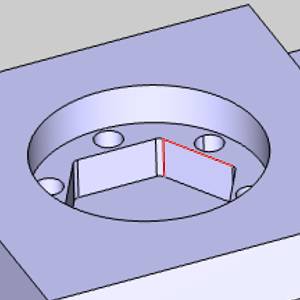
Click the Pick button in the Start group to set the start position.
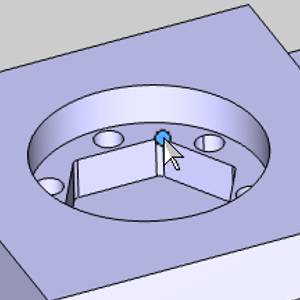
The Toolpath Pattern Dialog hides and selection mode is enabled. -
Click the
 .
.
The Toolpath Pattern dialog returns.
Part 4) Set the Positions
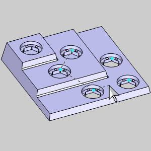
The Start and Positions determine the distances of our toolpath duplicates from the originals. Since we have used the Pick option to select our Start, we will use the Pick Positions option to select our Positions.
-
Click Pick Positions.
The Toolpath Pattern Dialog hides and selection mode is enabled. -
Take care to select the matching
-
Click
OK.
The Toolpath Pattern dialog returns.
Part 5) Set the Machining Order
The last group in the lower right of the Toolpath Pattern dialog box, is Machining Order. This group will allow you to select from Optimized, or Pick Order. To have control over the order our copies are machined in, we will need to set the Machining Order to Pick Order.
-
Click the Pick Order option in the Machining Order group.
-
Click
OK.
The Toolpath Pattern dialog closes.
The toolpath will now be machined in the order the Positions were selected.
Part 6) Simulate the Program
-
To view the part being cut, right-click
 Milling Job,
and click Simulation.
Milling Job,
and click Simulation.
To learn more about using Simulation, view Getting Started with Simulation.
The resulting stock model is shown next.
-
To close the simulation, click
 Exit Simulation.
This concludes the tutorial.