Creating Milling Tool Holders
Introduction
In this topic, you learn how to create a Tool Holder and Tool Arbor. You also learn the distinction between the Tool Holder and Tool Arbor as it is defined for BobCAM. Once created, the tool holder/arbor can then be assigned to a tool to be used for gouge checking (multiaxis features) and simulation purposes.
Tip: When creating tool holders, any changes that are made in the dialog box affect the currently selected item. Make sure that you have the proper item selected before making any changes.
Steps:
Part 1) How to Open the Milling Tool Holder Library
To access the Milling Tool Holder Library, do one of the following:
-
In the

 CAM Defaults, and click Mill ToolHolders.
-
In the
 Milling Tools, and click Mill ToolHolders.
(You can also click Assign Tool Holder in the Milling Wizard Tool page to assign a holder to the tool for the operation.)
The Milling Tool Holder Library dialog box appears with the default tool holders. On the left side, a Tool Holder category is selected, and all of the tool arbors for that category are listed on the right.
Part 2) How to Add and Name a Tool Holder Category
-
To add a new Tool Holder Category, in the Holders group, click Add Holder.
The Tool Holder Definition dialog box displays. -
To name the new holder, In the Holder Description box, type My Holder 1.
Part 3) How to Create a Tool Holder
-
To define the first element, in the Element List, click Cylinder.
In the Element Parameters list, type the following values.
|

|
-
To define the next element, in the Element List group, click AddCylinder, and type the following values.
|
|

Be sure to click the arrow next to Top Chamfer, and then click Top Fillet.
-
Click Add Cone, and type the following values.
|
|
-
Click Add Cone.
After adding this cone, you realize that a cylinder is needed before the cone.
Instead of deleting the cone, click Add Cylinder.
To reorder the elements, click Move Up.
With the cylinder selected, type the following values.
|
|
-
In the Element List, select the cone that was previously added, and type the following values.
|
|
-
Click AddCylinder, and type the following values.
|
|
-
To finalize the new tool holder, click OK.
In the Milling Tool Holder Library, notice that the new Tool Holder Category (My Holder 1) displays on the left side.
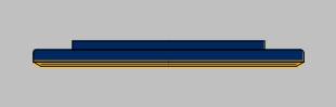
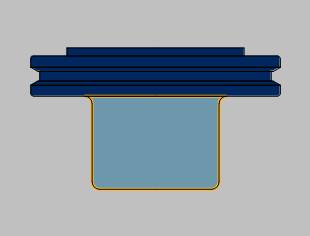
This now completes the process of making a Tool Holder and category. The geometry only includes the portion of the tool holder that is exposed from the spindle down to the bottom of the V-flange. The rest of the tool holder, below the V-flange, is classified as the tool arbor. The tool arbor is created next.
Tip: The center section (V-flange) of the tool holder uses multiple cylinders and cones. To create a chamfer that is not 45 degrees, you use a cone. To create a 45 degree chamfer, you use a cylinder with the chamfer option.
Part 4) How to Create a Tool Arbor
The tool holder created in the previous part is a CAT 50 end-mill holder. Since there is already a CAT 50 tool holder category, there is no need for My Holder 1. The next step is to eliminate this category in order to add the new tool arbor in the default CAT 50 category. This keeps all CAT 50 tool holders/arbors together in one category. In addition, when you use Delete Holder, the entire category, including the holder and all arbors, is deleted. When you use Delete Arbor, you are only deleting a single arbor.
-
To delete the unnecessary holder category, first make sure that My Holder 1 category is selected, and in the Holders group, click Delete Holder.
A message displays to confirm that you want to delete the selected holder.
Make sure that My Holder 1 is in this description, and click Yes. -
In the Tool Holder Category list, select CAT 50 Holder.
To create an arbor within this category, in the Arbors group, click Add Arbor.
Notice that the Tool Holder Definition dialog box displays the defined tool holder.
The first arbor element, in this case the default cylinder, starts at the bottom of the tool holder. -
To name the arbor, in the Arbor Description box, type 1.0 inch I.D. x 3 Arbor CAT 50.
This description is the label used when you assign a tool holder/arbor to a tool. -
Since the first element of the arbor is a cylinder, in the Element Parameters group, type the following values.
|
|
-
In the Element List, click AddCone, and type the following values.
|
|
|||||||||||||
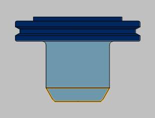
Tip: The cylinder element (step 4) has a diameter of 1.97 with a bottom fillet of 0.118. The cone element (step 5) has a diameter of 1.97 with a top fillet of 0.118. When two elements share the same diameter where they meet, you can apply a fillet across the two elements. To apply the fillet across the two elements, you must use the same fillet value for each element (Top Fillet of one element and the Bottom fillet of the next).
-
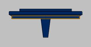
To finalize the new tool holder/arbor, click OK.
You have added a stubby CAT 50 tool arbor to the CAT 50 category.
How to Measure Angle Mode
|
Bottom Angle Mode = 45 degrees |
|
|

A Final Note on Creating Tool Holders
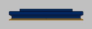
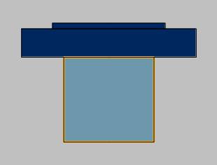
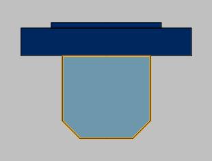
This tutorial is designed to show you how detailed you can be when creating tool holders. Although you have the ability to create an accurate tool holder model, this may not be necessary. The more detailed the tool holder is, the longer the calculation times are for simulation. Keep this in mind when creating tool holders. If you want to keep the calculation time a short as possible, you can use very simplified tool holders as shown next.
|
|
|
This concludes the tutorial.