Mill Turn Job Setup Example
Introduction
This topic explains how to create the Mill Turn job, stock, and machine setups for the Mill Turn Example 1 tutorial (but applies to any Mill Turn job). These items are already defined in the example file provided for the tutorial, so this topic provides the complete steps for those who want to learn more about the job setup.
Overview
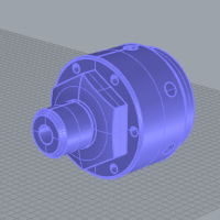
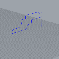
We have created our part model and lathe profiles in the location and orientation that we want to use, so we are ready to create the job, stock, and two machine setups.
Example File Download
The BobCAD part file for this tutorial is available for download at:
http://bobcad.com/helpfiles.
If you are connected to the Internet, you can click the link provided
to download and save the Mill Turn Job
Setup Example
This tutorial highlights the following functionality of the BobCAD-CAM software:
-
Creating a Mill Turn job
-
Adding Machine Setups to the job
-
Defining Stock using the Stock Wizard
-
Defining the Machine Setup parameters
-
Setting the spindle per setup
-
Aligning the machining origin
-
Defining the Work Offset parameters
-
Automatic Mill Turn Clearance settings
-
Assigning Workpiece geometry
Part 1) Create the Mill Turn Job
-
In the CAM Tree Manager, right-click
 CAM Defaults, and click New Job.
-
Under Job Type, click to select Mill Turn.
-
Under Machine, click the down arrow, and select BC_2T_2S.
Note: Normally, we would click Stock Wizard now to go directly to defining the stock and machine setup. For this example, we are utilizing two machine setups (one for the front of the part and one for the back), so instead we create a second machine setup first. This allows us to define both machine setups at the same time.
-
Click OK to create the Mill Turn job and add it to the CAM Tree Manager.
Part 2) Add the Second Machine Setup
- In the CAM Tree, right-click Mill Turn Job, and click Add Setup.
Note: This adds another machine setup after the
last machine setup in the CAM Tree. (Machine Setup 2 is added below Machine
Setup 1.)
(Alternatively, you can right-click any Machine
Setup, point to Additional Functions, and click Insert Setup. This adds
another setup below the selected setup.)
We are now ready to create the stock and define both machine setups.
Part 3) Create Stock Geometry Using the Stock Wizard
-
Right-click Stock, and click Stock Wizard.
-
Under Stock Type, click to select Cylindrical, and click Calculate Stock.
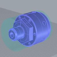
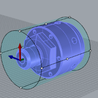
The software automatically detects the solid model in the graphics area and creates a bounding stock. We can see that the default extrusion direction (Z Axis) needs updated for our part orientation.
-
Under Stock Orientation, change the Extrusion Direction to Y Axis, and click Calculate Stock.
-
In the Dimension / Offset group, under Offset, change the Diameter value to 7.000, and press Tab to update the stock preview.
-
Change the Start Face Offset value to 3.000.
Change the End Face Offset value to 3.000.
-
Click
 to go to the
Machine Setup. (You may need to scroll down to see the button.)
to go to the
Machine Setup. (You may need to scroll down to see the button.)
Part 4) Define Machine Setup 1
Select the Machine Setup and Spindle
-
Notice at the top of the Machine Setup window that Machine Setup - 1 is selected. We use this machine setup for all features that machine the front half of the part model.
-
Confirm that the default, Left Spindle, is selected as this machine setup is created for the main (left) spindle.
Set the Machining Origin
-
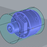
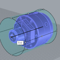
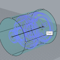
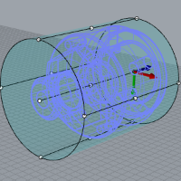
Next we define the machining origin for Machine Setup 1. You can see that the software automatically created bounding entities in the graphics area to assist with the origin selection.
-
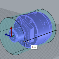
Under Setup Orientation, click in the Origin list box to enable selection mode.
-
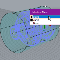
Move the mouse pointer to the point at the front of the part so that the point displays in the highlight color.
-
Click the point (while highlighted) to select the machining origin location.
Modify the Direction of the Machining Origin Axes
Next we modify the direction of the machining origin axes to align it to the machine zero (coordinate system). We need the Z-axis to be at the center line or rotation axis of the part to match the Z-axis of the machine, and we need our lathe profiles in the XZ plane of the machining origin.
-
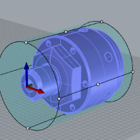
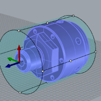
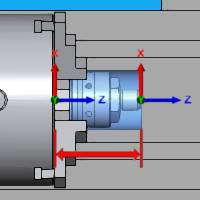
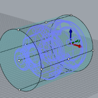
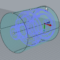
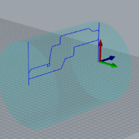
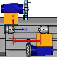
Under Origin, click the X Direction button, and click to select the point at the top of the arc entity shown next.
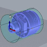
Notice that we are able to modify the direction by selecting a point. The X-axis direction of the machining origin updates (shown by the red arrow) based on our geometry selection.
-
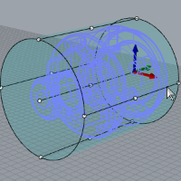
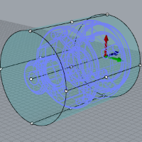
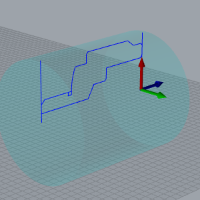
Click the Z Direction button, and click to select the line on the side of the part.
Note: For Mill Turn jobs, you have the freedom to create and orient the part any way that you like, thus you can also orient the machining origin as needed to accommodate your part orientation. An important note here is that the lathe profiles you create to assign to machining features must be in the XZ plane of the machining origin as shown next.
This is the reason for
the alignment we are using. (The red
arrow of the gnomon indicates the positive X-axis direction and the blue
arrow indicates the positive Z-axis direction.)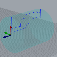
The Z-axis direction of the machining origin
is now parallel to the selected line.
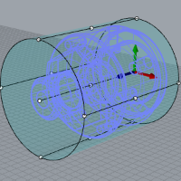
We want our machining origin to be zeroed
at the face of the part and not the stock, so next we adjust the origin
location.
Modify the Origin using the Enter Origin Method
-
Under Coordinate System, click in the Y value box behind the current value.
-
With your cursor behind the Y value, type +3.000. Press Tab to update the value and notice that the software allows for arithmetic operations in the text boxes.
Note that we are changing the Y-axis value because our machining origin Z-axis is aligned with the Y-axis of the WCS (CAD origin). The Enter Origin values are in reference to the WCS.
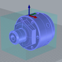
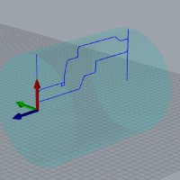
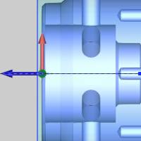
The machining origin updates to the front face of the part (instead of the front of the stock). (The following image uses the Left view as well as the transparent view to better show the new machining origin location.)
Define the Work Offset Parameters
-
Under Other, click the Work Offset button.
-
In the Work Offset dialog box, notice that Work Offset #1 is selected by default. We use this offset number for Machine Setup 1.
-
Update the Z value to 127. This defines the distance from the virtual machine zero to the machining origin (in Z). This value is used later for simulation purposes.
-
Update the Subspindle Z value to 127.
This defines the distance between the virtual machine zero and the front face of the sub spindle. You use this value to determine the location to which sub spindle moves when transferring the part. (This value is only used for simulation purposes.)
Note: The Part Pickup Position parameter in the Part Transfer MDI command may need adjusted based on the value defined (Subspindle Z).
-
Click OK to close the dialog box.
Define the Clearance Settings
-
Click the Clearance button.
-
Notice in the Clearance dialog box that the Auto check box is selected under Stock Bounds.
Because our stock and machining origin are already properly defined, the Stock Bounds parameters are automatically detected and populated.
Important: The software automatically calculates the clearance (Stock Bounds) settings based on the stock geometry and the machining origin location and orientation. For this reason, you should define the machining origin before modifying the clearance settings, as the Stock Bounds parameters may not be correct otherwise. The software automatically sets values in the CAM Wizards based on the values in the clearance dialog box.
-
Notice the Clearance settings for Face, Diameter, and Internal Diameter.
-
You can click in the box for each of these values to update the image in the dialog box to show where these clearance values apply.
For this example, we use the default values.
-
Click OK to close the dialog box.
Machine Setup 1 is now completely defined.
Part 5) Define Machine Setup 2
Because we already added the second machine setup to the job, we can now define the second machine setup. For the remainder of this example, we use the ISO 3 view found in the document toolbar.
Select the Machine Setup and Spindle
-
In the Machine Setup window, click the down arrow next to Machine Setup - 1 and click Machine Setup - 2.
We use this machine setup for all features that are created to machine the back half of the part model (on the sub spindle).
-
Click Right Spindle, as this machine setup is created for the sub (right) spindle.
Set the Machining Origin
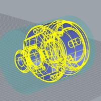
To accomplish this more easily, set the window to Wireframe.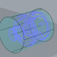
-
Click the Origin button and select the point entity at the back of the model.
(You could also click near the end of the
line in the center to get the same origin location.)
Modify the Direction of the Machining Origin Axes
Again, we must align the machining origin to use the appropriate direction for each axis.
-
Under Origin, click in the Z Direction list box, and select a line parallel to the rotation axis.
-
Next to Z Direction, click the
 (reverse)
button.
(reverse)
button.
-
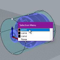
Click the X Direction button, and click to select the arc near the top point. (The software automatically uses the closest snap point of the entity to set the direction.)
Note: Notice again that we are aligning our X and Z axes (the XZ plane) of the machining origin to match the plane in which we created our lathe profiles.
We have accomplished the same X Direction as the first setup, but this time we selected a different bounding entity (the arc). When selecting geometry for the origin or axes directions, the snap point of the entity that is closest to the location you click is used.
We want this machining origin to be zeroed at the face of the part, so next we adjust the origin location as we did for the first machine setup.
Modify the Origin using the Enter Origin Method
-
Under Origin, click Enter Origin.
-
In the Y box, leave the current value and type -3.000 at the end of it. (This time we use a negative value because the direction is now opposite of the previous.)
-
Press Tab to update the value (14.00).
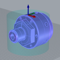
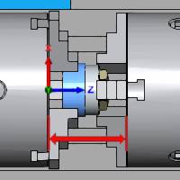
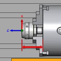
The machining origin updates to the back face of the part. (The left view and transparency are used in the following image.)
Define the Work Offset Parameters
-
Click the Work Offset button.
-
Next to Work Offset # click the down arrow and select 2.
We use Work Offset #2 for the sub spindle and all features created under Machine Setup 2. These features machine the back half of the part.
-
Update the Z value to 51.000. This defines the distance from the face of the sub spindle to the machining origin.
-
Notice that the Spindle Park Position value is already set to 914.4. The software automatically set this value based on the initial position of the sub spindle defined in the machine definition.
The Spindle Park Position defines the distance between the virtual machine zero and the front face of the sub spindle. This determines where the sub spindle sits while machining operations are performed on it.
We use the default value for this example to provide the maximum amount of clearance from other machine components (the main spindle) when working on the sub spindle. Depending on the size of your machine, you may want to change the park position to reduce the amount of sub spindle movement during the program if a large amount of clearance isn't needed.
-
Click OK to close the dialog box.
Define the Clearance Settings
-
Click the Clearance button to open the Clearance dialog box.
Because we have properly defined our machining origin, the Stock Bounds parameters are automatically set from using the Auto option.
-
Again, we use the default Clearance values.
-
Click OK to close the dialog box.
Machine Setup 2 is now completely defined.
-
Click OK to finish the Machine Setup.
Part 6) Additional Job Setup Tasks
Hide the Stock Geometry
It is often helpful to hide the stock geometry while creating machining features, to make it easier to view the toolpath. You may also want to show the stock quickly for verification purposes. The following steps explain how.
-
In the CAM Tree, right-click Stock, and click Blank.
The stock geometry is hidden from view.
-
To show the stock again, repeat step 1 or use the following step.
-
Click the Stock item in the CAM Tree and notice that the stock geometry temporarily displays in the graphics area. It displays until you click another tree item, such as Mill Turn Tools. You can use this tip to quickly display the stock and confirm a toolpath is correct.
Workpiece Assignment
Workpiece assignment in BobCAD-CAM allows you to assign geometry to be used as the workpiece in simulation (usually the model). When you run the Stock Wizard from the Machining Job dialog box, the Workpiece Assignment displays before the stock wizard. This dialog does not display when you open the Stock Wizard from the CAM Tree, as we did in this example. Next we show you how to assign the workpiece from the CAM Tree.
-
In the CAM Tree, right-click Workpiece, and click Re/Select.
-
Click to select the model in the graphics area.
-
Click
 to confirm
the selection.
to confirm
the selection.
Now that a workpiece is assigned, only the selected geometry displays (as the workpiece) in simulation regardless of what geometry is visible in the graphics area. Be aware that if you hide the assigned workpiece geometry, then the Workpiece button becomes unavailable in simulation. After assigning the workpiece geometry, you can click the Workpiece item in the CAM Tree to highlight the geometry in the graphics area.
Load the Tool Crib
The next step of the process is to load the Tool Crib for the job. More information is provided about loading and mounting tools in the Mill Turn Tutorials topic as well as in this Help system.
Related Topics
Mill Turn Tutorials