


 Parameters
Introduction
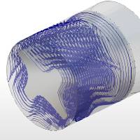
This topic explains the Parameters page of the 4 Axis Advanced Rough operation found in the Mill 4 Axis Rotary Wizard.
 Parameters
Finish
Depth Options
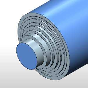
![]() Constant Depth Step - determines the maximum amount of material removed for each pass. Type the positive value that you want to use for each depth step. The software automatically calculates the appropriate number of steps.
Constant Depth Step - determines the maximum amount of material removed for each pass. Type the positive value that you want to use for each depth step. The software automatically calculates the appropriate number of steps.
- Depth of Cut - assigns the depth of cut.
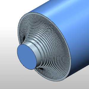
![]() Adaptive Depth Step - adjusts the depths within the defined range so flat areas can be machined that could not be reached with a constant depth step.
Adaptive Depth Step - adjusts the depths within the defined range so flat areas can be machined that could not be reached with a constant depth step.
- Depth of Cut - specifies the maximum depth per pass.
- Minimum Depth of Cut (%) - specifies the minimum allowable depth based on 100% being the full Depth of Cut.
- Force Floor Cuts
 - With this check box selected, the floors and steps will not be cut unless they fall into the allowable cuts defined by the Depth of Cut and, when Adaptive Depth Step is used, the Minimum Depth of Cut (%).
 - With this check box selected, cuts will be made on the floors and steps.
|
|
|
|
|
- Stepover - specifies the distance between each pass.
- Machining Tolerance - the amount of variation allowed for creating the toolpath for the feature. The accuracy of the toolpath does not exceed this range.
Limits
- Axial
- Does not put any restriction on the distance of cuts along the axis. - Allows you to specify start and/or end distances to limit the area of toolpath engagement along the axis. 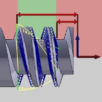
- Start - specifies the distance, from the machine setup, at which to begin the toolpath.
- End - specifies the distance, from the machine setup, at which to end the toolpath.
- Start - specifies the distance, from the machine setup, at which to begin the toolpath.
- Radial
- Does not put any restriction on the distance of cuts along the radius. - Allows you to specify start and/or end distances to limit the area of toolpath engagement along the radius. 
- Start - specifies the distance, from the machine setup, at which to begin the toolpath.
- End - specifies the distance, from the machine setup, at which to end the toolpath.
- Start - specifies the distance, from the machine setup, at which to begin the toolpath.
- Conical
- Does not put any restriction on the distance of cuts along the conical angle. - Allows you to specify start and/or end distances to limit the area of toolpath engagement along the conical angle.
These images are being shown as cross sections of a conical part for simplicity. Please see the note at the bottom of the section for clarification.- Start - specifies the positive or negative distance, from the extension of the conical angle, at which to begin the toolpath.
- End - specifies the positive or negative distance, from the extension of the conical angle, at which to end the toolpath.
- Start - specifies the positive or negative distance, from the extension of the conical angle, at which to begin the toolpath.
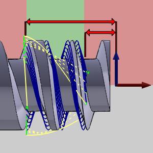
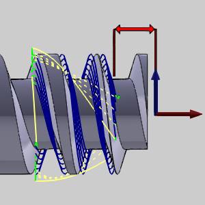
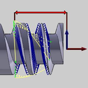
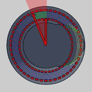
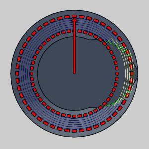
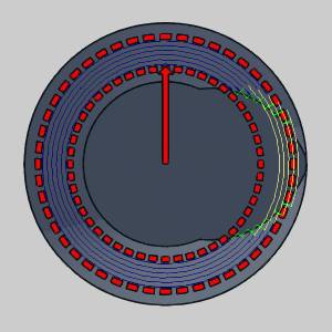
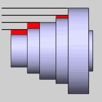
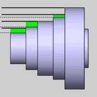
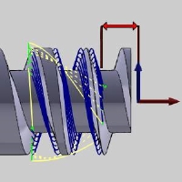
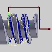
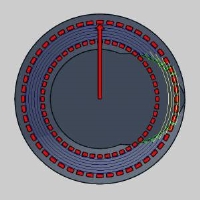
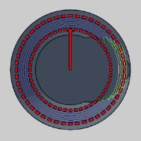
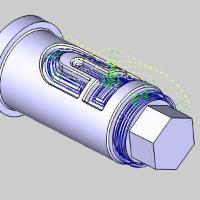
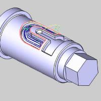
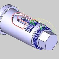
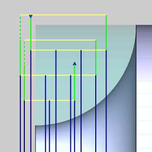
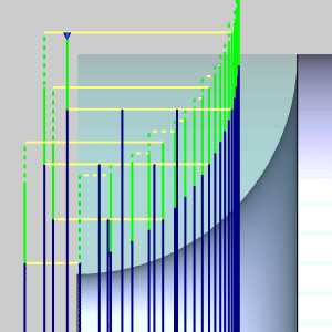
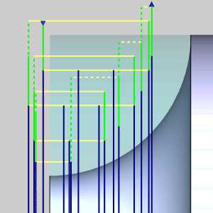
Important: Conical limits are determined by 'placing' the conical angle at the Base Point location. The start and end distances are then referenced as offset from the extensions of this conical angle. Limits inside the conical angle are negative, while those outside are positive. Click the gifs below to see this represented with the green cone representing the same conical angle but within features with two different Base Point values. The red cone represents the Start limit and the blue represents the End limit.
| Negative values | Positive values: |
|
|
Bounds
-
Trim to Stock
Clear the check box to create the operation without trimming the toolpath
to the stock.
Select the check box when you want the software to trim the toolpath for
the operation to the stock in one of two ways. You can (1) assign a solid
model or .stl file using the Operation Stock item in the CAM Tree, or
(2) if you don't assign operation stock, the software automatically uses
the stock from the Stock Wizard to trim the toolpath. View Selecting
Operation Stock.
Tip: You can use simulation to save the stock model as an .stl file, which can then be used as Operation Stock. To learn more, view How to Save Simulation Stock as STL.
-
Invert Boundary
Clear the check box to contain the toolpath inside the boundary.
Select the check box to keep the toolpath outside the boundary.
| No Boundary | ||
|
|
|
Allowance
-
Allowance XYZ - the distance that the toolpath is calculated from the model geometry. Positive values leave material remaining for a finish pass without having to offset the model geometry.
Advanced
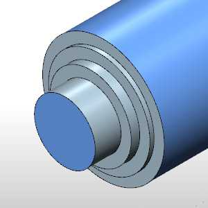
- Detect Stock Thicker Than - Will allow you to set a particular value which will represent the stock thickness at which no additional cuts are needed. With this value set to 0.125, only steps in the stock that are thicker than this will have intermediate steps used on them. With this value set to zero, the Intermediate Steps will be applied against the model between every step.
|
|
|
|
|---|---|---|
| ...Stock Thicker Than 0.000 | ...Stock Thicker Than 0.025 | |
|
|
|
|
|
|
Related Topic
Click Next> > to move on to the Leads page.