In this Topic Show
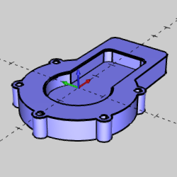
This topic explains how to create the CAD model for the Mill Express demonstration file. The design process includes using the Shape Library, 2D Boolean, and other wireframe functions to create the profile, pocket, and holes for the model. The wireframe is then extruded to create a boss, and the pocket and holes are removed from the boss using extruded cuts.
This tutorial highlights the following features of the BobCAD-CAM software:
Using the Shape Library
Utilizing entity colors and CAD layers to aid in geometry selection
Creating Hole Patterns
Creating and managing CAD layers
Deleting geometry
Using 2D Boolean to add wireframe chains
Using Quick Trim
Using Extrude Boss
Using the Snap Increment to eliminate data entry changes
Using Extrude Cut
Creating chamfers with Solid Fillet
Using Tangent Propagation to your advantage
A template file is provided so that you can have the same system colors as shown in this tutorial. We start by opening the template file and renaming it to keep the original file unchanged. It is good practice to always begin a file by saving it with an appropriate name and location and then saving often.
1 In the File menu, click Open.
Navigate to C:\BobCAD-CAM Data\BobCAD-CAM V29\Examples\Demo Files, and select Getting Started Template.bbcd.
Click Open.
2 In the File menu, click Save As.
Select or create a new folder to save to, or just use the Demo Files folder.
In the File Name box, type Mill Ex CAD, and click Save.
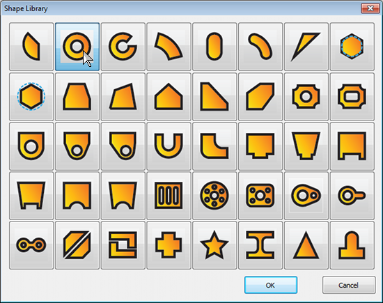
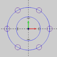
We use the Shape Library to quickly create wireframe geometry that is modified later.
1 In
the Other menu, click ![]() Shape
Library.
Shape
Library.
Select the  ring shape,
and click OK.
ring shape,
and click OK.
2 In
the ![]() Data Entry
Manager, update the parameters as follows:
Data Entry
Manager, update the parameters as follows:
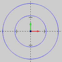
1 = 4.000
2 = 2.250
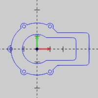
Notice that the CAD preview of the shape updates as you define the Data Entry parameters. The CAD preview allows you to confirm the desired result before creating the shape.
Under Position and Orientation:
X = -2.000
Y = -2.000
3 Click OK to create the shape.
4 Click Cancel to close the Data Entry Manager.
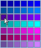
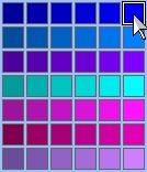
Next we change the active entity color before creating the hole pattern. This assists in geometry selection later in the tutorial.
1 In
the lower-right corner of the user interface, click the entity color down
arrow  .
.
2 In the color palette, select the purple color (row 3 column 1).
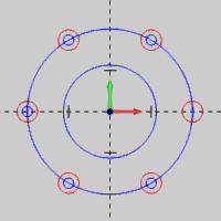
Now we use a hole pattern to easily create a circular pattern of holes.
1 In the Other menu, click Hole Pattern.
2 Update the Data Entry parameters:
Dia. (Diameter) = 4.000
Hole Diameter = 0.500
Click Break.
Number of Holes (X) = 6
Under Origin, click Center.
3 Click OK to create the hole pattern.
Before creating another hole pattern, we change back to our original drawing color.
1 Click
the entity color down arrow  .
.
2 In the color palette, select the blue color (row 1 column 6).
Using CAD layers is a great way to keep your drawings organized. This helps with geometry selection and provides a convenient way to hide and show geometry.
1 Right-click
anywhere in the ![]() Layers
Manager window, and click Add
New Layer.
Layers
Manager window, and click Add
New Layer.
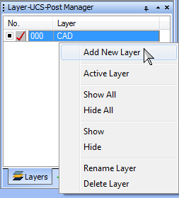
2 To name the layer, type Holes, and press Enter to update the name.
3 Right-click the layer name Holes, and click Active Layer.
The next set of holes is created on the active (Holes) layer.
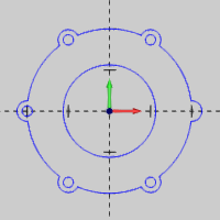
Now we create the second hole pattern, which is later used to extrude cut holes into the model.
IMPORTANT: Generally, when you modify the Data Entry settings for a CAD function, such as Hole Pattern, they are retained until you change them again or close the file or software. After closing a file and/or the software, the Data Entry settings return to their default values. In this example, we only instruct you to change values as needed, based on this understanding. So, when defining the Hole Pattern explained next, all settings should be the same as the previous Hole Pattern, and you should only update the values as explained. (For example, Break is still selected from the previous pattern.)
1 Change the Hole Diameter to 0.250, and press Tab to update the CAD preview.
Click OK.
2 Click Cancel.
3 In the File menu, click Save.
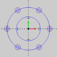
This part shows you how to delete existing wireframe geometry.
1 In the Edit menu, click Select Mode.
2 Click, or drag a window, to select the small (0.250 diameter) circle at the three o' clock position.
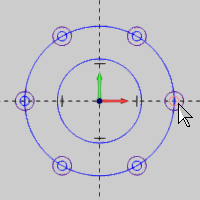
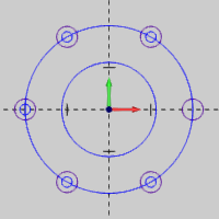
3 Press the Delete key. (Alternatively, in the Edit menu click Delete).
We only want the second hole pattern on the Holes layer, so now we set the CAD layer as active.
1 In
the ![]() Layers Manager,
right-click CAD, and click Active Layer.
Layers Manager,
right-click CAD, and click Active Layer.
Notice the red check mark (![]() ) indicates the active layer.
) indicates the active layer.
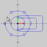
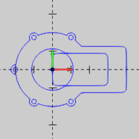
Next we boolean add two closed wireframe chains to begin defining the outside profile for the model.
1 In the Utilities menu, click 2D Boolean.
Notice that Add is selected in the Data Entry Manager.
2 Click to select the largest circle as the first closed chain.
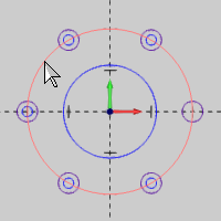
To confirm the selection, click ![]() .
.
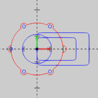
3 In the Edit menu, point to Select Entities, and click Pick+Match Color.
4 Click to select any one of the purple circles.
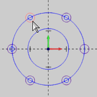
Notice that all matching geometry is automatically selected.
5 Click OK.
6 On
the selection toolbar, click  to turn off the Pick+Match Color selection filter.
Click Cancel.
7 Press Ctrl+S to save the file.
The next steps involve creating two rectangles that are used to complete the outer profile and the pocket.
1 In the Other menu, click Rectangle.
2 Update the Data Entry parameters:
Length (X) = 4.000
Width (Y) = 2.500
Under Corner Type, click Radius. (Use the default value of 0.250.)
Under Origin, click the down arrow and select Left.
Click OK to create the first rectangle.
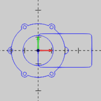
3 Update the Data Entry parameters:
Length (X) = 3.000
Width (Y) = 1.750
Click OK to create the second rectangle.
4 Click Cancel.
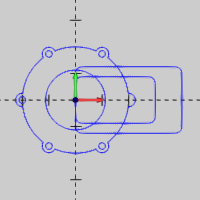
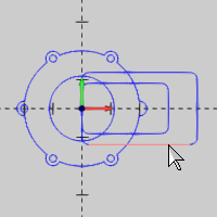
We use 2D Boolean again to finish creating the outer profile.
1 On
the CAD toolbar, click ![]() .
.
Confirm that Add is selected.
2 Press and hold Shift, and click the outer arc to chain select the entire chain.
To confirm the selection, press Spacebar.
3 Hold Shift, and click to chain select the larger rectangle.
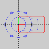
4 Click OK.
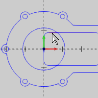
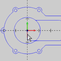
Now we take a moment to use the wireframe trimming tool, Quick Trim. Quick Trim is one of the many useful trimming tools in BobCAD-CAM, and it allows you to delete whole entities or trim them to the intersection of other entities.
1 In the Utilities menu, point to Trim/Extend, and click Quick Trim.
Click all of the entities that are inside of the circle and rectangle, in the center of the part, until you have created a single profile for the pocket. (There are seven total selections.)
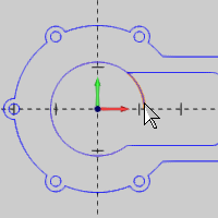
2 Click Cancel.
Save the file.
In this part, we create a layer to hold only our solid model. One method of utilizing layers is to create them as needed for certain entities or groups of entities to organize your drawings.
1 Right-click in the Layers Manager, and click Add New Layer.
2 Type Solids to name the layer, and press Enter.
3 Next
to Solids, click ![]() to set it as the active
layer. The
to set it as the active
layer. The ![]() icon changes to
icon changes to ![]() .
.
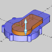
We now extrude our wireframe profile to create the main body of our solid model.
1 Press Ctrl+7 to select the ISO2 view. (Alternatively, in the View menu, point to Views, and click ISO2.)
2 In the Solids menu, click Extrude Boss.
3 Hold Shift, and click anywhere along the outer profile to chain select it.
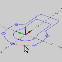
4 Click OK to create the preview.
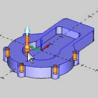
5 Click the upper (positive) sketch handle to activate sketching.
Move the sketch handle down past the selected geometry and into the negative (other) direction.
TIP: In this step, we are dragging the extrusion preview from the positive direction down into the negative (other) direction. When you reach the geometry, the positive distance becomes zero, and BobCAD-CAM automatically switches from the positive sketch handle to the negative sketch handle to allow you to easily change the extrusion direction.
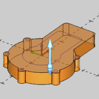
Notice that the Data Entry parameters automatically update while moving the sketch handles. Now we utilize the snap increment to get the exact value without the need for data entry.
6 Move the sketch handle until the Distance value (under Other Direction) becomes 0.750, and click to anchor the sketch handle.
Click OK.
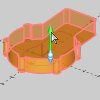
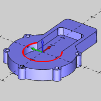
The next steps show how to use Extrude Cut to cut the pocket and holes into the model.
1 In the Solids menu, click Extrude Cut.
2 Press S to turn off the shaded view. (Alternatively, in the View menu, click Shaded.)
TIP: The Shaded and Transparent view options can be utilized to aid in the selection of surface edges, or as in this example, wireframe that is on a surface. You can press S or T to toggle these view options.
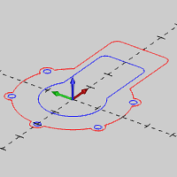
3 Hold Shift, and click the wireframe profile of the pocket.
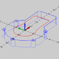
Click ![]() .
.
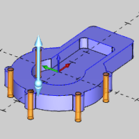
4 Press S to turn on the shaded view.
5 Under Other Direction, update the Distance value to 0.500.
6 Click OK.

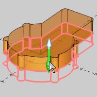
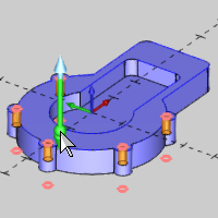
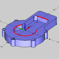
1 In the Edit menu, point to Select Entities, and click Pick by Layer.
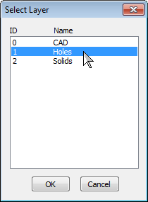
Click Holes, and click OK.
2 Click OK to create the CAD preview.

3 Use the lower sketch handle to extend the extrude completely through the part.
TIP: When creating through holes with Extrude Cut, it is generally not important that the Distance values are exact. You can either type the exact value, or use sketch handles to extrude up to, or past, the surface you are cutting.
4 Click OK.
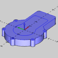
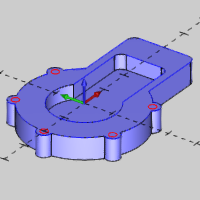
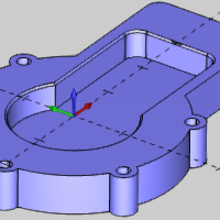
The final step of creating our model is to apply a small chamfer to the internal pocket edge using solid fillet.
We hide the layers that contain our wireframe geometry as it isn't needed anymore, and because we need to select the surface edges of the pocket (not the wireframe used to create it).
1 Right-click the CAD layer, and click Hide.
2 Next
to Holes, click ![]() , so it changes to
, so it changes to ![]() .
.
The layer visibility button is another way to hide and show layers.
Only the Solids layer should be visible.
When creating solid fillets or chamfers, you can reduce the number of selections needed by using Tangent Propagation. Tangent Propagation automatically applies (propagates) the fillet to any edges that are tangent to your selections. In this part, we show that you only need to select two of the six edges to apply a chamfer around the entire pocket.
1 In the Solids menu, click Fillet.
2 In the Data Entry Manager, click the down arrow and select Chamfer.
3 Change the Chamfer value to 0.050.
Notice that Tangent Propagation is selected by default.
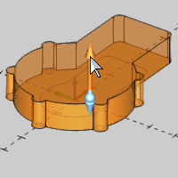
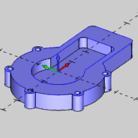
4 Click to select the circular edge at the top of the model.
TIP: The circular edge is selected because it forms sharp corners with the edges on either side of it. Any other edge can be selected next, and Tangent Propagation automatically applies the chamfer to the entire pocket. (If the sharp corners were made with a small radius instead, only one edge would need to be selected.)
5 Select any other surface edge at the top of the pocket.
Click OK.
6 Click Cancel.
7 Save the file.
Congratulations! You have finished the Mill Express demonstration CAD model.
To learn how to machine the model, view the Mill Express CAM Tutorial.