 Machine
Setup.
Machine
Setup.The counter bore example follows the same procedure as the other hole making features. The only difference is in the geometry selection. Follow this lesson to create a Counter Bore feature, toolpath and NC program.
Click File, Open
Select HoleExample.SLDPRT (C:\BobCAM Data\BobCAM V2\Examples\HoleExample.SLDPRT)
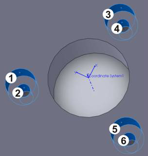
You must assign a Coordinate System to the Machine
Setup.
To insert a Counter Bore Feature:
In the  BobCAM CAM tree, right-click
(click the right mouse button)
BobCAM CAM tree, right-click
(click the right mouse button)  Milling Stock, click Drill to open the Hole
Wizard
Milling Stock, click Drill to open the Hole
Wizard
Click Counter Bore Hole, Next to move to the Geometry Selection page
To associate the geometry with the feature:
Click Select Geometry
Click the two cylindrical faces of each of the three counter bore holes as shown next
Click  ,
Next, Finish
to exit the Hole Wizard
,
Next, Finish
to exit the Hole Wizard
NOTE: After inserting a Counter
Bore feature, you can also select the feature geometry by right-clicking
 Geometry
and clicking Re/Select from the
CAM tree.
Geometry
and clicking Re/Select from the
CAM tree.
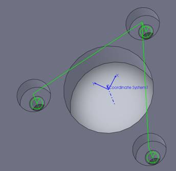
To compute the toolpath:
In the
BobCAM CAM tree, under  Feature Counter Bore Hole, right-click Counter
Bore Hole, click Compute Toolpath
Feature Counter Bore Hole, right-click Counter
Bore Hole, click Compute Toolpath
The result should look like the following image
To post the NC program:
In the CAM tree, under
 CAM Part, right-click
  Milling Tools
Click Post,
the NC program is displayed in the ![]() Posting
tab
Posting
tab
This concludes the basic process of creating a Counter Bore feature, toolpath and NC program. For more information on selection options, view Counter Bore Selection.