 Machine
Setup.
Machine
Setup.Read this tutorial to learn the basic concepts of creating Turning features. A lathe part is used to create a Rough feature followed by a Groove feature. A toolpath is created for each feature and afterwards, the NC program code is posted. Click the links to learn more about machine setup, geometry selection, and detected feature geometry for primary and secondary regions.
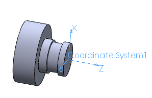
You must assign a Coordinate System to the
Machine
Setup.
To insert a Rough feature:
In the  BobCAM CAM Tree tab, right-click
 Turning
Stock
Turning
Stock
Click Turn, Rough
To associate the geometry with the feature:
Under  Feature Rough, right-click
 Geometry,
click Re/Select to open the
Selection Manager
Geometry,
click Re/Select to open the
Selection Manager
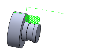
Select all of the faces
of the part, click  OK
OK
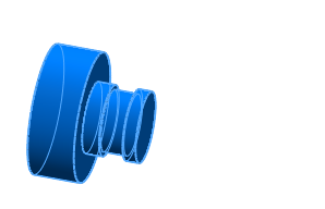
More about Geometry Selection
Click
Feature Rough to view the
Detected Feature Geometry
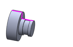
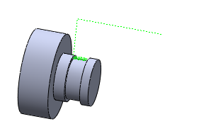
About Detected Feature Geometry:
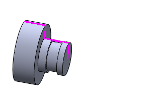
In the Selection Manager there are two options, Remove First Vertical Line and Remove Last Vertical Line, which are selected by default. This is shown in the preceding image. The result is that no facing is performed by the Rough feature. If you want to face the part with the Rough feature, clear the appropriate check box. The result is shown in the following image with the Remove first vertical line check box cleared:
More about detected feature geometry and Primary and Secondary Regions
To compute the toolpath:
In
the CAM Tree, under
Geometry, right-click  Rough, click Compute
Toolpath
Rough, click Compute
Toolpath
To insert the Groove feature:
In the
CAM tree, right-click
Turning Stock
Click Turn, Groove
To associate the geometry with the feature:
Under
Feature Groove, right-click
Geometry, click Re/Select
to open the Selection Manager
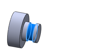
Select the three faces
of the groove, click
OK
To compute the toolpath:
Under
Geometry, right-click Groove, click Compute Toolpath
To post the NC program:
In the CAM tree, under  CAM Part, right-click
  Turning Tools
Click Post,
the NC program is displayed in the Posting
tab ![]()
This concludes the basics of creating Turning features.