The Rectangle function is used to create rectangles using sketching, data entry, or a combination of both.
Rectangle supports Dynamic Drawing which allows you to use data entry and/or sketching to create rectangles. After sketching a rectangle, it becomes the active entity. The active entity displays in the current Entity color, but displays with a greater line thickness to make it easier to identify. The active entity can then be modified using data entry. The benefit of Dynamic Drawing is that you can quickly sketch a rectangle to get the approximate result and then use data entry to update it to exact coordinate values as needed.
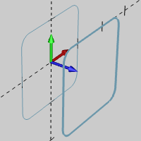
Active Entity
Rectangle supports the use of the snap increment when selecting the origin location or, when using the Sketch Free option, the corners of the rectangle. The snap increment allows you to get precise results when using mouse selection and helps to reduce data entry modifications.
To learn more, view Snap Increment.
To open Rectangle, do one of the following:
In the Other menu, click Rectangle.
On the CAD toolbar,
click the ![]() icon.
icon.
Right-click anywhere in the graphics area, point to CAD, Other, and click Rectangle.
The parameters display in the ![]() Data Entry tab
of the Data-CAM Tree Manager.
Data Entry tab
of the Data-CAM Tree Manager.
![]() Select the check
box to set the sketch mode to require two clicks, one for each opposing
corner to define the rectangle. The snap increment applies when you select
for each corner of the rectangle.
Select the check
box to set the sketch mode to require two clicks, one for each opposing
corner to define the rectangle. The snap increment applies when you select
for each corner of the rectangle.
![]() Clear the check box to set the sketch mode to require one click to place
the Origin of the rectangle using the current Length and Width values.
The snap increment applies when you select the origin location using the
mouse.
Clear the check box to set the sketch mode to require one click to place
the Origin of the rectangle using the current Length and Width values.
The snap increment applies when you select the origin location using the
mouse.
Radius - creates the rectangle with round corners using the Radius value.
Chamfer Length - creates the rectangle with chamfered corners using the Chamfer value.
Sharp Corner - creates the rectangle with sharp corners.
The Origin determines the coordinate location of the rectangle using the XYZ coordinates of the active UCS. The selected origin location determines where the origin is on the entity (also called the reference location).
Reference Location
The Rectangle function allows you to set the origin to the center or any corner or side of the rectangle. The XYZ coordinates determine the location of the selected origin/reference location.
X - is the X-axis location of the entity origin.
Y - is the Y-axis location of the entity origin.
Z - is the Z-axis location of the entity origin.
IMPORTANT: The XYZ coordinates are in reference to the active UCS, or user coordinate system.
1 Open the function and click a snap point or anywhere in the graphics area to set the origin of the rectangle.
When you select the Sketch Free check box, you click to select the two opposing corners of the rectangle in the graphics area (the origin location in the Data Entry Manager does not apply in this scenario).
With either method, you can modify the snap increment value or turn it off while selecting locations with the mouse.
2 This is now the active entity, which means that it is not fully defined.
IMPORTANT: After sketching a rectangle, it changes from the Preview color to the current Entity color, but displays with a greater line thickness (than existing entities) to show that it is the Active entity. You can then modify the Data Entry parameters to update the active entity.
3 Dynamic Drawing allows you to update the Data Entry parameters to modify the active rectangle.
After updating the Data Entry parameters, to finish the active entity, you can click OK or start sketching the next rectangle.
When you don't need to update the Data Entry parameters, you can just click to start the next rectangle.
NOTE: There are many ways to finish the active entity: click OK, press Spacebar, or click in the graphics area to start the next rectangle.
4 Repeat this process for all rectangles that you want to create.
5 To close the function, click Cancel.
You can also create rectangles using only data entry.
1 Open the function and define all Data Entry parameters needed for the first rectangle.
2 Click OK to create the rectangle.
3 Update the Data Entry parameters, and click OK to create the next rectangle.
4 Repeat this process for as many rectangles as needed.
5 To close the function, click Cancel.