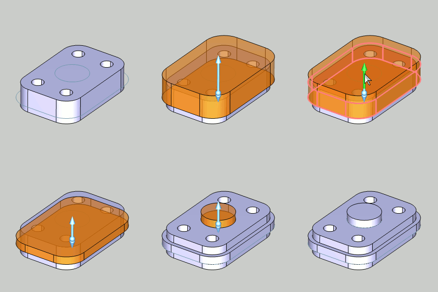
 Extrude Boss
 Extrude Boss
The Extrude Boss function creates solid bodies by extruding closed wireframe chains or planar surface geometry and automatically joins the intersecting (touching) entities into a single solid. When using a surface, the software automatically extracts the edges of the surface to use for the boss.
TIP: Extrude Boss automatically merges all intersecting solids into a single solid body, unless they are hidden using the View menu Blank function. Hiding a layer does not exclude the entities on that layer from being merged by Extrude Boss. To extrude geometry that does not automatically merge with other solid bodies, use Extrude Curve or Extrude Surface.
Extrude Boss supports Dynamic Drawing which allows you to use sketch handles to modify the extrusion distances, which can also be defined using data entry. The benefit of Dynamic Drawing is that you can use the sketch handles to roughly define the extrusion and then use data entry to accurately update the distances as needed.
To learn more about Dynamic Drawing, view Dynamic Drawing for Solids.
Extrude Cut supports the use of the snap increment when using the sketch handles to set the distance values. The snap increment allows you to get precise results when using mouse selection and helps to reduce data entry modifications.
To learn more, view Snap Increment.

To open Extrude Boss, do one of the following:
 icon.
icon.
The parameters display in the ![]() Data Entry tab of the Data-CAM Tree Manager.
Data Entry tab of the Data-CAM Tree Manager.
The Selected Geometry list, shows all the selected entities to be extruded.
![]() (Delete) - removes the selected
entity from the Selected Geometry list.
(Delete) - removes the selected
entity from the Selected Geometry list.
![]() (Delete
All) - removes all entities from the
Selected Geometry list.
(Delete
All) - removes all entities from the
Selected Geometry list.
Draft Angle - creates an angle along the edge of the extruded shape in the positive direction. This also applies to any internal shapes when you select more than one curve to extrude. This can be a positive or negative value.
Draft Angle - creates an angle along the edge of the extruded shape in the negative direction. This also applies to any internal shapes when you select more than one curve to extrude. This can be a positive or negative value.
Along Normal - the extrusion occurs parallel to the normal direction of the plane created by the selected curve.
Along
Z-Axis - the extrusion direction is the Z-axis regardless of
how the selected curve is oriented.
1 Open the function and define all Data Entry parameters.
2 Select geometry in the Workspace.
This can be closed wireframe chains or planar surface geometry. When using a surface, the software automatically extracts the edges of the surface to use for the boss.
3 Click
![]() (OK) to confirm the selection and create the CAD
preview.
(OK) to confirm the selection and create the CAD
preview.
You can modify the snap increment value or turn it off if you are using sketch handles.
If needed, use the dynamic sketch handles or data entry to update the CAD preview.
To learn more about Dynamic Drawing, view Dynamic Drawing for Solids.
4 In the Data Entry tab, click OK to create the entity.
The feature is added to the CAD Tree.
5 Click Cancel to close the function.