 Shell Solid
 Shell Solid
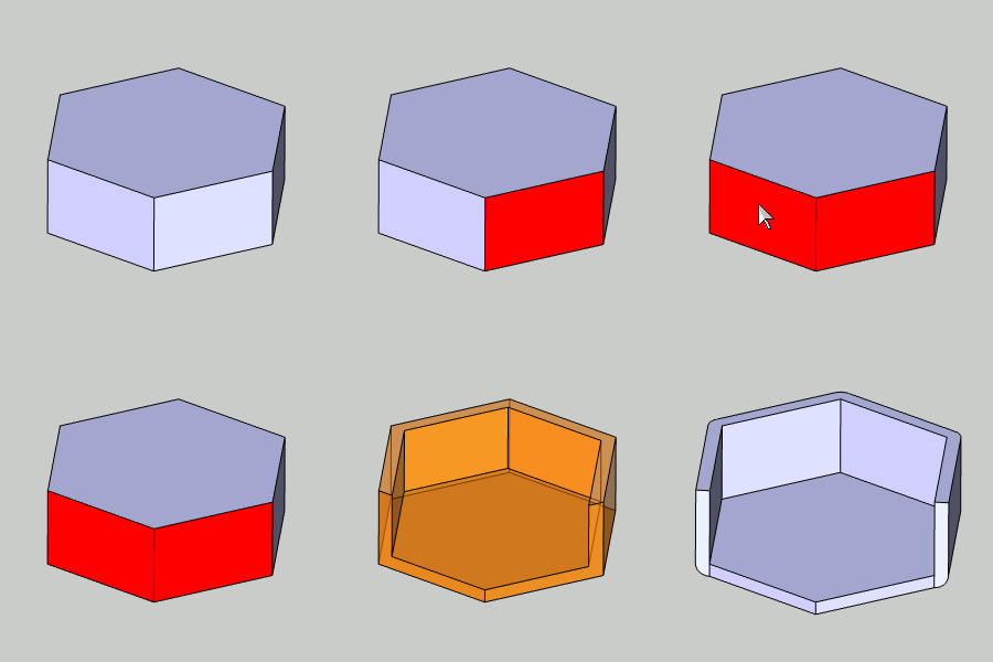
The Solid Shell function is used to remove one or more faces of a solid body and recreate the solid with the specified wall thickness for the remaining surfaces. You can also shell the whole solid to create a closed hollow solid.

To open Shell Solid, do one of the following:
 icon.
icon.
The parameters display in the ![]() Data Entry tab of the Data-CAM Tree Manager.
Data Entry tab of the Data-CAM Tree Manager.
 Whole Solid
- With this checkbox cleared, selection mode will be set to individual
surface faces only.
  Whole Solid - With this checkbox
selected, selection mode will be set to solid bodies only.
Selected Geometry
This will list the entities the shell function will be applied to.
![]() (Delete) - removes the selected
entity from the Selected Geometry list.
(Delete) - removes the selected
entity from the Selected Geometry list.
![]() (Delete All) - removes all entities
from the Selected Geometry list.
(Delete All) - removes all entities
from the Selected Geometry list.
The direction parameters determine which way the shelled solid is created from the original solid.
 Inward - when this option is selected, the
shell will be created by offsetting inward from the original geometry.
 Outward - - when this option is selected,
the shell will be created by offsetting outward from the original
geometry.
Wall Thickness - is the thickness for the resulting surfaces of the shelled model.
 Fillet Edges - creates fillets for all resulting
shelled surface edges. This option uses the Wall Thickness parameter
for the fillet radius.
 Fillet Edges - does
not create fillets.
IMPORTANT: The Fillet Edges parameter is applied to outward shell creation, and is very important for creating successful shelled surfaces. Turning this option on or off can often resolve failed calculations. The Fillet Edges option uses the Wall Thickness as the fillet radius so the dimensions of the original solid must allow this radius to be applied.
Once geometry has been added to the Selected
Geometry list, selecting this toggle will enable, and disable the CAD
preview, which displays the result that will be created when you click
OK.
OK - performs the function to create the geometry shown in the CAD preview.
Cancel - closes the Data Entry Manager.
1 Open the function and define all Data Entry parameters.
2 Click
to select one or more faces of the solid that you want to remove.
You can perform the function on one or more solids.
3 Once geometry is added to the Selected Geometry list, click Show Preview to see a preview of the result.
4 If
needed, update the Data Entry parameters.
The changes update the CAD preview.
5 Click
OK to create the shell.
The feature is added to the CAD Tree.
6 Repeat this process as needed for any other solids, if you want to create another shell with different parameters.
7 Click Cancel to close the function.