 icon.
icon.This topic provides an example of how to use the Shell Solid function. This topic is supplemental to Shell Solid.
A BobCAD file installed with the software can be opened to follow along with this example.
1 In the File menu, click Open.
2 Navigate to: C:\BobCAD-CAM Data\BobCAD-CAM V**\Examples, and select Shell Solid Example.bbcd.
3 With Shell Solid Example.bbcd displaying in the File Name box, click Open.
To open Shell Solid, do one of the following:
icon.
The parameters display in the  Data Entry tab of the Data-CAM Tree Manager.
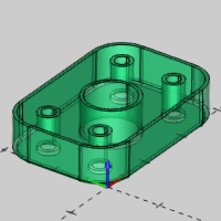
For this example, we select the geometry first to create the CAD Preview before updating the Data Entry parameters. This allows us to visualize the effect of each parameter and the result before actually creating it.
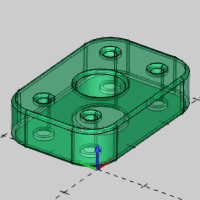
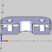
1 Click to select the top face of the part as seen in the image below.
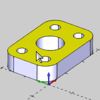
The selected face is added to the Selected Geometry list.
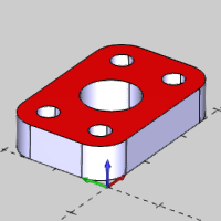
2 Click Show Preview to create the CAD preview.
3 In the Data Entry Manager, under Direction, click Outward.
The Direction option determines to which side of the original surfaces the Wall Thickness is applied.
4 Double-click in the Wall Thickness box, to select all the text, and type 0.0625.
Press Tab or click anywhere in the graphics area to update the CAD preview.
The Wall Thickness is applied to all surfaces and it also determines the radius value when using the Fillet option.
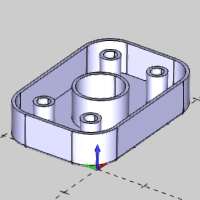
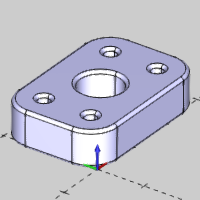
5 To
shell the solid as shown in the CAD preview, click OK.
The Shell is created in the graphics area and a ![]() Shell feature is created in the
Shell feature is created in the
![]() CAD Tree.
CAD Tree.
6 Click Cancel to close the Data Entry Manager.
After using Shell Solid, a feature is created and added to the CAD Tree to allow for modification and more as explained in the CAD Tree. When you cancel the function, the CAD Tree Manager automatically displays. Notice the Shell feature in the CAD Tree.
1 Click the Shell feature in the CAD Tree and notice that the result highlights in the Workspace.
2 Next
to Shell, click  to expand the feature.
The Geometry item contains a right-click shortcut menu that can be used to modify the selection and update the feature. For this example, we edit the feature to show how to use Shell Whole Solid.
3 Right-click Shell, and click Edit Parameters.
The Edit Parameters option opens the function with the geometry preselected for you to change only the parameters. If you use the Edit option, the function is opened without the geometry preselected.
You can also use the Shell Whole Solid option to create a hollow solid body. When using this option, no faces are removed from the model.
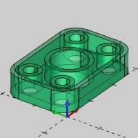
1 In the Data Entry Manager, click Whole Solid.
In this scenario, changing to Shell Whole Solid clears the geometry selections, because we are changing the way that the Shell function works by changing the selection mode.
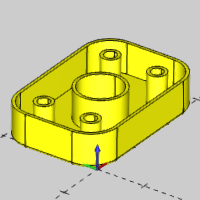
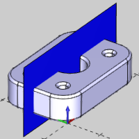
2 Click
to select the flange in the graphics area.
Notice that you can now only select the entire solid, not separate faces
as earlier.
3 Press the Show Preview button to create the CAD preview.
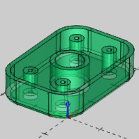
4 Click OK to shell the whole solid.
The Data Entry Manager is automatically closed when you click OK after editing.
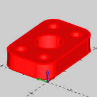
When using the Shell Whole Solid option, the result is not easy to visualize because you are creating a hollow solid. After using Solid Split on our shelled solid, you can easily see the part is a hollow solid model.
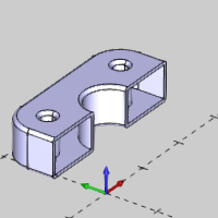
This concludes the example.