The Nonuniform Scale function is used to scale (resize) wireframe or solid entities with separate scaling factors for each of the three coordinate axes.
TIP: To use Nonuniform Scale on text entities, you must either create them using the Vectorize option, or you can use the Explode utility after creating non-vectorized text. Either method converts the text entities to lines and arcs so they can be used with Nonuniform Scale.
To open Nonuniform Scale, do one of the following:
In the Utilities menu, click Nonuniform Scale.
On the Utilities toolbar,
click the ![]() icon.
icon.
Right-click anywhere in the graphics area, point to Utilities and click Nonuniform Scale.
The parameters display in the ![]() Data Entry tab
of the Data-CAM Tree Manager.
Data Entry tab
of the Data-CAM Tree Manager.
![]() Select the check box to enable the CAD preview, which displays the result
before you create it. The preview is created when you confirm the selections.
Select the check box to enable the CAD preview, which displays the result
before you create it. The preview is created when you confirm the selections.
![]() Clear the check box to turn off the CAD preview. The geometry is scaled
when you confirm the selections.
Clear the check box to turn off the CAD preview. The geometry is scaled
when you confirm the selections.
The scale factor determines the ratio of scaling applied to the geometry in each of the three dimensions. A value of 1.00 is equal to no scaling, 0.50 is equal to one half of the original size, and 2.00 is equal to twice the original size.
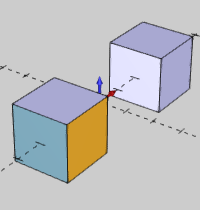
As a reference for the Location Control options, the following image shows the original geometry that is selected together for the function. One of them is a single solid and the other is separate (unstitched) surfaces, shown in multiple colors.
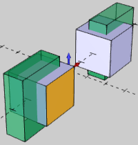
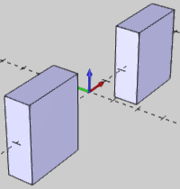
NOTE: The example image shows that all seven entities (one solid and six surfaces) are scaled as a single entity. Notice that the location of each cube changed. If you scaled each cube separately using the same parameters, the location would not change.
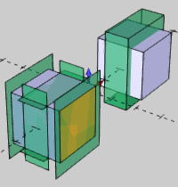
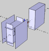
Notice the difference in the result between the separate surfaces (left cube) and the single solid cube (right cube.)
1 Open the function and define all Data Entry parameters.
2 Select all entities that you want to scale with the current settings.
This can be solid or wireframe geometry.
TIP: To use Nonuniform Scale on text entities, you must either create them using the Vectorize option, or you can use the Explode utility after creating non-vectorized text.
3 To
confirm the selections and create the CAD preview, click ![]() (OK).
(OK).
If you turned off the CAD preview, the geometry is scaled when you confirm the selections. Using the CAD preview allows you to update the parameters before scaling the geometry.
4 If needed, update the Data Entry parameters. (The CAD preview updates to reflect the changes.)
If you want to scale more entities, update the Data Entry parameters and repeat this process as needed.
5 To close the function, click Cancel.
If you selected solid or surface geometry to scale, a feature is added to the CAD Tree.