This topic provides an example of how to use the Nonuniform Scale function. This topic is supplemental to Nonuniform Scaling.
A BobCAD file installed with the software can be opened to follow along with this example.
1 In the File menu, click Open.
2 Navigate to: C:\BobCAD-CAM Data\BobCAD-CAM V**\Examples, and select Nonuniform Scale Example.bbcd.
3 With Nonuniform Scale Example.bbcd displaying in the File Name box, click Open.
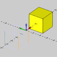
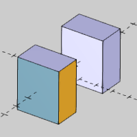
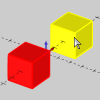
The example file contains two cubes, one of which is a single solid body, and the other is unstitched meaning it is six separate surfaces (solid bodies). This is done to help illustrate the scaling options for the function.
Before opening the function, we use the CAD Tree to visualize the solid bodies in the graphics area.
1 In
the Data-CAM Tree Manager, click
the ![]() CAD Tree Manager
tab.
CAD Tree Manager
tab.
2 Next
to ![]() Solids,
click
Solids,
click ![]() to expand the folder.
to expand the folder.
3 Click anywhere in the graphics area, to give it key focus, and press S to turn off the Shaded view. (Alternatively, in the View menu, click Shaded.)
4 Click Solid 1 in the CAD Tree and notice the cube highlights in the graphics area.
5 Click each Solid item in the CAD Tree to highlight the separate surface bodies in the graphics area.
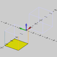
You can see that one cube is a single entity, and the other cube is six separate entities.
To open Nonuniform Scale, do one of the following:
In the Utilities menu, click Nonuniform Scale.
On the Utilities toolbar,
click the ![]() icon.
icon.
Right-click anywhere in the graphics area, point to Utilities and click Nonuniform Scale.
The parameters display in the ![]() Data Entry tab of the Data-CAM Tree Manager.
Data Entry tab of the Data-CAM Tree Manager.
For this example, we select the geometry first to create the CAD preview. This allows us to view the result of the function before it is created.
1 Press S to turn on the Shaded view.
2 Press Ctrl+A to select all geometry in the graphics area. (Alternatively, in the Edit menu, click Select All.)
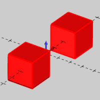
Click OK to create the CAD preview.
It appears as if there is no CAD preview, because we have not yet defined a Scaling Factor (they are set to 1.00 which means no scaling).
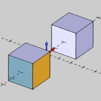
3 In the Data Entry Manager under Scale Factor, double-click in the X box to select all the text, and type 0.750.
Press Tab to move to the Y box and update the CAD preview.
This setting scales the geometry to 75 percent of the original size in the X-axis only.
4 In the Y box, type 1.250 and press Tab.
This setting scales the geometry to 125 percent of the original size in the Y-axis only.
5 In the Z box, type 1.500 and press Tab.
NOTE: When scaling 2D wireframe entities, only two of the Scale Factors can be used, based on the drawing plane. For example, changing the Z-axis scale factor has no effect on wireframe drawn in the XY plane.
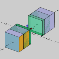
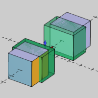
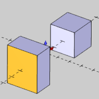
We have been using the default Location Control option, Scale All Entities Together. This treats all selected geometry as a single unit to which the scaling is applied. You may notice that the CAD preview shows the cubes are moving away from their original location as a result of the current Location Control option. Next we explore the Scale Each Entity Individually option.
1 Under Location Control, click Scale Each Entity Individually.
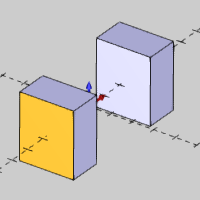
Notice the change in the CAD preview. You can see that the scaling is no longer moving the cubes away from their original location, because they are now being scaled as individual entities. You can also see that each surface of the unstitched cube is now also being scaled individually.
TIP: Using the Scale All Entities Together option maintains the relationship between multiple entities when using nonuniform scaling. This may be helpful when scaling wireframe shapes, or as in this example, a cube made of separate surfaces.
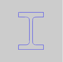
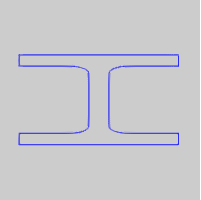
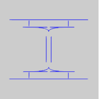
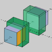
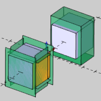
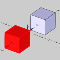
Original Shape |
Scale All Entities Together |
Scale Entities Individually |
|
|
|
Note that both Location Control options provide the same result when scaling a single entity.
2 Change the Location Control back to Scale All Entities Together.
3 To scale the entities as shown in the CAD preview, click OK.
4 Click Cancel to close the Data Entry Manager.
When you use Nonuniform Scale with solids, a feature is created and stored in the CAD Tree to allow for modification and more as explained in the CAD Tree. When you cancel the function, the CAD Tree Manager automatically displays. Notice the Nonuniform Scale feature in the CAD Tree.
For this part of the example, we decide that we want to scale each of the cubes individually. Next we use the CAD feature to change the geometry selection.
1 In
the CAD Tree next to Nonuniform Scale,
click ![]() to expand the feature.
to expand the feature.
2 Right-click
![]() Geometry,
and click Re/Select.
Geometry,
and click Re/Select.
3 Click the single-entity cube to remove it from the selection.
4 Press the Spacebar to confirm the selection.
Notice that the feature automatically rebuilds when confirming the selection.
Now that we are scaling each cube separately, they retain their original location (the center of the cube doesn't change).
5 You can now create another Nonuniform Scale feature to scale the other cube.
This concludes the example.