CAM
Tree, right-click
CAM
Tree, right-click  CAM
Defaults, and click Current Settings.
CAM
Defaults, and click Current Settings.In this Topic Show
The Current Settings dialog box controls various machine and posting parameters. You define and modify the machines that you use in order to create proper NC programs and simulation. Setting these options to reflect what the machine is capable of is an important part of properly setting up the software. The settings in this dialog box apply to the selected machine and are saved when you click OK. When you click Save As Default, the machine and the current settings are used as the default for each new file that is created (this determines the default machine listed for each job type in the Machining Job dialog box).
The Current Settings dialog box parameters change slightly depending on the type of machine that is selected on the first page (Machine Parameters). This topic explains all of the parameters that display for mill, lathe, waterjet, laser, plasma, or mill-turn machines. To learn about the available settings for Wire EDM machines, view the Current Settings Default for Wire EDM topic.
To access the Current Settings Default dialog box to set the system defaults (for new files):
CAM
Tree, right-click CAM
Defaults, and click Current Settings.
To access the Current Settings Job dialog box and update settings for the current job only:
CAM
Tree, right-click the job
folder (for example,
Milling Job), and click Current
Settings. Machine Parameters
The Machine Parameters page of the Current Settings is used to select a default machine, modify an existing machine, or to create a new machine. All of these actions are performed using the Machine group as explained next. When you select a machine in the Machine group, all of the parameters contained in the Current Settings dialog box (for all pages) pertain to that machine.
Make - displays the make/name of the currently selected machine. To update the Current Settings dialog box with all of the parameters for a machine, click the arrow, and select a machine. You can then modify the parameters as needed. These are saved when you click OK. To use the current selection and settings for all new files, click Save As Default.
Type - displays the machine type that is defined during machine creation.
Add - opens the Add/Modify Machine dialog box for you to create a new machine as explained in the next section.
Delete - removes the selected machine. A dialog box displays, click Yes to delete the selected machine.
Modify - opens the Add/Modify Machine dialog box for you to change the name of the machine. For Milling machines, the type can be changed to Laser, Plasma, or Waterjet.
Save As Default - saves the current machine and all parameters as the default machine for all new files (for the corresponding machine/job type).
Number of Axes - displays the number of axes of the selected machine (when a mill, lathe, waterjet, laser, or plasma machine is selected).
Auto Tool Numbering By Device (Mill Turn Machines Only)
When you select a mill turn machine under Make, the Auto Tool Number By Device check box becomes available. This setting determines how the stations of the machine's tool device are numbered in the Tool Crib. This then determines how the Tool ID and Tool Numbering options you select in the Tool Crib work. (For more information, view Mill Turn Tool Crib Parameters.) Selecting the check box considers each tool device on the machine as its own component (by device). Clearing the check box considers all tool devices on the machine together as though they are one device (globally) as explained next.
 On - determines the tool numbering by device.
For example, on a machine with two six-station turrets, both turrets
contain station numbers 1 through 6 in the Tool Crib. When more
than one tool is mounted to a station, the additional tools for
each turret use ID/number 7 through n
number of tools.
On - determines the tool numbering by device.
For example, on a machine with two six-station turrets, both turrets
contain station numbers 1 through 6 in the Tool Crib. When more
than one tool is mounted to a station, the additional tools for
each turret use ID/number 7 through n
number of tools.
 Off - determines the tool numbering globally.
For example, on a machine with two six-station turrets, the first
(upper) turret contains station numbers 1 through 6, and the second
(lower) turret contains station numbers 7 through 12 in the Tool
Crib. When more than one tool is mounted to a single station,
the additional tools for either turret use tool ID/number 13 through
n number of tools.
Off - determines the tool numbering globally.
For example, on a machine with two six-station turrets, the first
(upper) turret contains station numbers 1 through 6, and the second
(lower) turret contains station numbers 7 through 12 in the Tool
Crib. When more than one tool is mounted to a single station,
the additional tools for either turret use tool ID/number 13 through
n number of tools.
Machine Name - type the name of the machine you are creating.
Type - set the machine type: Milling, Laser, Plasma, Waterjet, Lathe, Wire, or Mill Turn.
NOTE: The Axes option does not display when a Lathe or Wire EDM machine type is selected.
Axes - select the number of axes/machine type for Milling, Laser, Plasma, Waterjet, or Mill Turn machines only.
When User Defined is selected, the Machine Definition tree is empty so you must create every element.
When finished with the Add/Modify Machine dialog box, click OK. A folder is automatically created in the BobCAD-CAM Data\...\MachSim folder using the Machine Name. This folder is used to store the machine information. This includes an .xml file of the machine definition and any files (.stl or .bmp) that are added in the Machine Definition dialog box that is explained later in this topic.
Machine Make - sets the machine manufacturer for Wire EDM machines only. (For Wire EDM Current Settings, view the Current Settings Default for Wire EDM.)
Maximum # of Tools - sets the number of tools the machine can use for one program.
Maximum Spindle Speed - sets the maximum speed rate for the spindle.
Rapid Feed - sets the rapid rate of the machine in units per minute.
Maximum Cutting Feedrate - sets the maximum feedrate for cutting.
TIP: The Maximum Cutting Feedrate is also used to determine the feedrate for some retract moves as well as adaptive link moves for toolpaths using Adaptive high-speed machining as listed next:
After defining the Machine Parameters, click Machine Definition to access the parameters used to create your machine. It is important to set up your machine properly in order to create proper simulation and posted NC programs.
 Machine Definition
The Machine Definition contains two groups: Machine and Machine Data. The Machine group contains a tree structure that shows all the parts/elements of the machine that are defined, such as the machine housing and axes. When you select an item, the information for that element displays in the Machine Data group. Most of the information can be edited in the dialog box. You can right-click an item in the Machine group to add or delete items. For example, you can right-click a linear Y-axis definition to add a rotational axis.
IMPORTANT: The Machine Definition is required for all Milling, Laser, Plasma, Waterjet, and Mill Turn machines. The Machine Definition is predefined for Lathe or Wire machines. When you select a Lathe or Wire machine (in the Machine Parameters page), the Machine Definition becomes unavailable (it is visible, but can't be modified).
The shortcut menu that displays when you right-click a Machine group item includes some or all of the following options.
Add Transl. Axis - allows you to add an X-, Y-, Z-, or User Defined-linear axis.
Add Rotational Axis - allows you to add an A-, B-, C-, or User Defined-rotation axis.
Add Coordinate Transform - allows you to add a Workpiece, Holder, Machine, or User Defined transform. This is used to define the position of the selected item on the machine table.
Add Dynamic Element - allows you to add a Workpiece Set or Tool Set. Each set contains multiple dynamic (or variable) components as listed next. After you add a set, you can then right-click the first item (Workpiece or Holder Transform) and select Add Dynamic Element to add a single item from the set. The following two elements must exist in the Machine tree, but understand that the geometry and position for these elements is generally defined by each program that you create. (The software automatically creates the geometry for each program based on the stock and tool parameters that you define in each job.)
Workpiece Set - contains the Workpiece Transform, Fixture, Initial Stock, Stock, Toolpath, and Workpiece tree items.
Tool Set - contains the Holder Transform, Tool, Flute Part, Shaft Part, Arbor Part, and Holder Part tree items.
Add Geometry - displays the Open dialog box for you to select an .stl file to use for any items that need geometry defined, such as the machine housing. Geometry should only be added to machine elements when you have the full machine simulation that is included in the Pro Simulation.
Add CollCheck - allows you to add a Tool-Workpiece or User Defined collision check. A tree item labeled cc is added. When you click cc, the Machine Data group shows three boxes. The large box on the left contains all the Machine group tree items. You select and add the item you want to check into the Group 1 box. You then select and add items to the Group 2 box. The items in Group 1 are checked for collisions with the items in Group 2.
Add Magazine - allows you to add a magazine to create a multiple-head machine.
Add Turret - adds a turret item to the tree for mill turn machines. Click the Turret item in the tree to display the Turret Name box and Turret Wizard button under Machine Data. You can right-click the Turret item to display a shortcut menu with the following options.
Edit - opens the Turret Configuration for you to define the parameters of the turret.
Add Geometry - displays the Open dialog box for you to select an .stl file that is used to define the turret geometry. If you do not add geometry, the turret definition from the Turret Wizard is used.
Delete - removes the turret item from the tree.
Add Milling Spindle - adds a milling spindle to the tree for mill turn machines. Click the Milling Spindle item to display the Milling Spindle Name box and Milling Spindle Wizard button under Machine Data. You can right-click the Milling Spindle item to display a shortcut menu with the following options.
Edit - opens the Milling Spindle Configuration for you to define the parameters of the milling spindle/head.
Add Geometry - displays the Open dialog box for you to select an .stl file that is used to define the spindle geometry.
Delete - removes the milling spindle item from the tree.
Delete - removes the selected item or group of items.
The machine data group lists the available
parameters for the item selected in the Machine group. The information
is usually presented in two columns. The column on the left is for display
and the column on the right is used to edit the parameters. You can click
in the box to make an edit. When you select a Machine Data item you may
see a  button appear on
the right side. For example, in the Machine group, select Head, and in
the Machine Data group, click Geometry. On the right side, click . The Open
dialog box displays for you to locate and select the proper .stl
file which defines the Head geometry. Instead of using the button, you can double-click
Geometry to accomplish the same task.
button appear on
the right side. For example, in the Machine group, select Head, and in
the Machine Data group, click Geometry. On the right side, click . The Open
dialog box displays for you to locate and select the proper .stl
file which defines the Head geometry. Instead of using the button, you can double-click
Geometry to accomplish the same task.
Important Notes for Creating Machines
When you create a machine, the Machine name and the folder in which it is stored must use the same name.
Each CAD file used to create a part of the machine must use the .stl file type.
When creating .stl files for each part of the machine, you should orient the parts based on an origin such as the center of the machine. For example, you use the CAD coordinate X0 Y0 Z0 as the machine center point. All parts are then drawn in reference to this location. When you align each .stl file to this origin before they are added to the Machine Definition, you can eliminate extra steps needed to properly align the machine parts.
If you are defining a mill-turn machine, click Submachine to define all submachines and parameters. Otherwise, after creating the Machine Definition, click Posting to access the posting parameters that are used for the selected machine. It is important to define the posting parameters in order to create proper NC program output.
Axis ID Manager (Mill Turn only)
When a mill turn machine is selected, the Axis ID Manager button displays below the Machine Data group of the machine definition. Click the Axis ID Manager button to open the Axis ID Manager dialog box. This dialog box allows you to reorder all axes of the machine to change their ID number/order. The Axis ID Manager is used to map the machine axes to specific blocks in mill turn post processors, so unless you are creating or modifying your post processor, you should not modify the axis ID numbers.
View Understanding the Machine Definition.
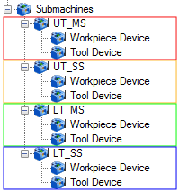
The Submachine page of the Current Settings displays when you select a mill-turn machine in the machine parameters. There are two groups in the submachine page: Devices and Parameters. The Devices group displays a tree structure that contains the machine, its devices, and submachines (work zones). The Parameters group is used to edit the parameters of the currently selected tree item.
The machine and the devices are automatically populated from the machine definition. The devices are a collection of machine components that work together to hold either the workpiece or tools, thus there are two device types: workpiece devices or tool devices. A workpiece device is a lathe spindle, or chuck, and a tool device may be a turret or a milling spindle. A submachine (work zone) is a combination of one workpiece device and one tool device. The submachine determines which machine devices/components work together to perform machining operations (work zone). You define the submachines based on how many potential device combinations exist on the physical machine.
Submachine Tree |
Submachines - Device Grouping |
 |
 |
The following is a general description of the Devices tree structure.
Level 2 contains the Devices and Submachines (parent items).
Level 3 displays the devices and submachines (child items).
Level 4 displays the actual devices (or machine components, such as linear or rotary axes) from the machine definition and the devices for each submachine.
When defining the submachines, you click an item in the Devices group and then use the Parameters group to edit any available parameters for that item (not all items in the tree can be edited). The submachine items in the tree are the only items that contain a shortcut menu, as described next.
To add a submachine:
To delete a submachine:
IMPORTANT: Before creating submachines, it is important to properly define the parameters for all devices that displays under the Devices tree item (level 3 of the tree). These parameters are explained in the following section of this topic.
There are many important settings for the Devices tree items that are only accessed in the Parameters group as explained next.
When you click a tree item in the Devices tree, the parameters for that item display in the Parameters group. This section explains all of the parameters that can be edited and their descriptions.
Devices
The devices are automatically populated using their names from the machine definition. When you click a device in the tree the following parameters become available. (You click in the box next to each parameter to edit its value.) You should properly define all parameters for all devices before adding the submachines.
NOTE: The child items of any device (such as a rotary or linear axis) are the same as shown in the machine definition, and they display for reference purposes. These items cannot be edited in the parameters group because they are defined in the machine definition.
Submachines
After defining the parameters for all machine devices, you can then add the submachines. When you click a submachine item in the tree, the following parameters display in the Parameters group.
ID - is the name used for the submachine. It is very important to name each submachine with a descriptive name that makes it easy for you to recognize. For example, a submachine can be named UT-MS to represent the upper turret, main spindle and LT-SS can represent the lower turret, sub-spindle submachine. The submachine ID (name) is used in various places such as the CAM wizards and tool crib.
Workpiece Device - must be set to the workpiece device used for the selected submachine. When you click in the box, a down arrow displays for you to click and select a device name (which uses the names defined in the Device tree).
Tool Device - must be set to the tool device used for the selected submachine. When you click in the box, a down arrow displays for you to click and select a device name (which uses the names defined in the Device tree).
First Linear Axis - must be set to the machine component (child of the device) that represents the X-axis for the submachine's tool device. For example, the machine definition may contain two X-axis elements and two Y-axis elements named X, XX, Y, and YY. Either X or XX would be assigned as the first linear axis.
Second Linear Axis - must be set to the machine component (child of the device) that represents the Y-axis of the submachine's tool device.
Third Linear Axis - must be set to the machine component (child of the device) that represents the Z-axis of the submachine's tool device.
First Rotation Axis - must be set to the machine component (child of the device) that represents the primary rotation axis for the submachine, usually the lathe spindle. This can be the primary/main spindle or a secondary/sub spindle.
Second Rotation Axis - is used for multiaxis mill-turn machines that contain a rotation axis other than the lathe spindles, such as a the B-axis of a milling spindle for multiaxis machines.
Submachine Devices
When you select the workpiece device or tool device of a submachine, its parameters display in the Parameters group. These parameters are generated from the machine definition. It is important to properly select the Name parameter for each device of the submachine. This does not change name of the component in the tree, but rather assigns the appropriate device to the component. When you properly define the submachine definition, the name should automatically be set to the appropriate device, but it is important to confirm.
 Posting
Select - displays the Open dialog box for you to locate and select a post processor to use for the selected machine.
Select - displays the Browse For Folder dialog box for you to locate or create a folder in which the posted NC program is stored.
NC File Extension - allows you to specify a file extension that is automatically added to the NC program file.
Number - is the program number as it appears in the posted NC program.
Post Setting - uses the post processor settings to define absolute or incremental posting values.
Absolute - uses absolute values only for posting.
Incremental - uses incremental values only for posting.
Start Number - designates the starting line number for events in the NC program if the machine is configured to output them.
Sequence # Increment - sets the number added to each subsequent line number for the next line.
Output Subprograms
Select the check box to generate repetitive subprograms in the posted
NC program, if the post processor is set up to do so.
Clear the check box when not generating subprograms.
The following two options are only available when the Output Subprograms check box is selected.
Subprogram Start # - sets the first subprogram number used in the NC program.
Subprogram # Increment - if more than one subprogram is generated, this value sets the number added to the previous subprogram number for the next.
This option is only available when a mill machine is selected in Machine Parameters.
GCode 4 Axis Arcs OK
Select the check box to output arcs in the NC program for 4-axis machining.
Clear the check box to output only points and line segments in the NC
program for 4-axis machining.
This option is only available when a lathe machine is selected in Machine Parameters.
Theoretical Point - calculates the toolpath from the theoretical point of the tool (the intersection of two tangent lines extending from the extents of the cutting area of the tool).
Cutting Arc Center - calculates the toolpath from the arc center of the tool (inside the extents of the cutting portion of the tool by the size of the tool nose radius).
Output Automatic Comments
Select the check box to allow the automatic comments from the post to
be output.
Clear the check box to not allow the automatic comments from the post
to be output.
After defining the Posting parameters, click Multiaxis Posting to define the additional posting parameters for your machine.
 Multiaxis Posting
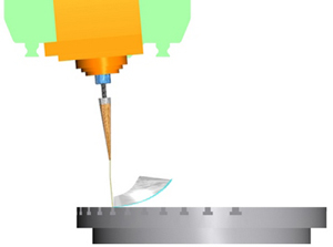
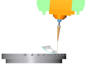
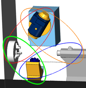
For many 5-axis machines there are two possible solutions to any point in a toolpath. The solution here refers to the angles used for each rotational axis. The following images show a part with the two possible Angle Pair solutions (this is the tool orientation for the toolpath starting point). The tool orientation to the part is the same in each situation; however, the table is rotated 180 degrees. The Angle Pair options control which solution is used. The purpose of the Auto Angle Pair is to use the solution that creates the least amount of tool-axis orientation change from the previous toolpath position. Keep in mind that some machines can't use both pairs based on rotational limits.
|
There are two main ways to set the Angle Pair settings: Automatic Angle Pair or Manual Angle Pair. These options are explained next.
Automatic Angle Pair
When the Automatic Angle Pair option is selected, the following parameters become available.
Select Between the Two Solutions
When selecting this option, the software attempts to use the angle pair that provides the least amount of machine movement (from the start of the toolpath or previous operation). You can select First Solution and allow the software to calculate the angles. If this setting does not provide the desired results, you can change it to Other Solution to use the other possible angle pair values.
Instead of using Select Between Two Solutions, you can provide a preferred first or second rotation Angle, and the software selects the solution closest to that value. Positive and Negative values can be used and the solution that is closest to the Provided Rotation Angle is used. For example, if you set the First Rotation Angle to 80 degrees, and the two possible solutions are: C = 90 degrees or C = -90 degrees, the post uses C = 90 degrees.
Provide 1st Rotation Angle
Select this option to make the angle box become available so you to type the preferred rotation angle for the first rotary axis. The software uses the closest possible value to the angle you enter.
Provide 2nd Rotation Angle
Select this option to make the angle box become available so you to type the preferred rotation angle for the second rotary axis. The software uses the closest possible value to the angle you enter.
There is one more Automatic Angle Pair option that depends on the currently selected Pole Handling option. When you set the Pole Handling option to Force Table Rotation, the following option becomes available under Automatic Angle Pair.
This option allows you to select the preferred translation axis that you want to use. The software uses the closest possible solution based on the axis you select. You can select the positive or negative direction for any of the three linear axes: 1st Linear Axis [+], 1st Linear Axis [-], 2nd Linear Axis [+], 2nd Linear Axis [-], 3rd Linear Axis [+], or 3rd Linear Axis [-]. What is important to understand is that these labels correspond to the linear axes defined in the machine definition. Generally, for most machines, the first linear axis is the X-axis, second is the Y-axis, and third is the Z-axis.
Manual Angle Pair
The Manual Angle Pair options provide another way for you to set the angle pair used for the machine.
After selecting this option, you can select either Solution 1 or Solution 2. If you are unsure which setting to use, leave the default and post the code. If this does not provide the desired solution, change to the other option.
When a four-axis machine is selected, the Angle Pair settings change to an optimized set that apply to these machine types. These options are explained next.
This setting allows the software to automatically calculate the appropriate angle to use for the rotary axis.
Provide Rotation Angle
This setting allows you to type the preferred rotation angle in the angle box. The software uses the closest possible value to the angle you type.
Provide Translation Axis
This option is unavailable until the Pole Handling setting is Force Table Rotation. This option allows you to select the preferred translation axis that you want to use. The software uses the closest possible solution based on the axis you select. You can select the positive or negative direction for any of the three linear axes: 1st Linear Axis [+], 1st Linear Axis [-], 2nd Linear Axis [+], 2nd Linear Axis [-], 3rd Linear Axis [+], or 3rd Linear Axis [-]. What is important to understand is that these labels correspond to the linear axes defined in the machine definition. Generally, for most machines, the first linear axis is the X-axis, second is the Y-axis, and third is the Z-axis.
The Machine Limits are used to confirm that the machine limits are not exceeded. When a program exceeds the set limits, it does not post. To set the Machine Limits, select a limit group from the Limits box and then type values for the following two parameters.
Angle Tolerance For Using Machine Limits - type a value from which the selected Machine Limits can vary. If you set Machine Limits for an axis between 0 and 90 degrees and set an Angle Tolerance of 2, then the possible range becomes -2 to 92 degrees.
Angle Change Limit - type a value in degrees to limit the amount of angle change from one toolpath position to the next. If an angle change exceeds this limit, then a retract move is applied in the post.
Limits box - select one of the following options to be affected by the Angle Tolerance and Angle Change Limit parameters:
No Limits
Translational Limits
Rotational Limits
All
Limits
When a five axis machine is used to run a 3-axis toolpath, there are certain situations that make the C-axis value arbitrary. What this means is that by changing the X- and Y-axis values appropriately, any C-axis value used creates the same results. For example, when a cylinder is located in the center of the table, depending on the machine, there are multiple ways to cut the profile of the cylinder. The rotation axis can be fixed while the linear axes are used to cut the part. On the other hand, the linear movements can be fixed, while the table is allowed to rotate in order to cut the part. This situation where the C-value is arbitrary, because the spindle direction and the table direction are collinear, is called a singularity or pole. The Pole Handling options are used to control these situations as follows.
Freeze Angle Around Pole - fixes the rotational axis in order to use the linear axes movements.
Use Rotation Angle Around Pole to Stay Within Linear Axis Limits - is used when a program exceeds the linear axis limitations. The extents of the linear movements are fixed in order to use the rotational axis as a substitute for the linear movement limitations.
Linear Interpolation of Rotation Angle Around Pole - calculates rotational axis values to make the changes from one value to the next in a linear fashion. The linear distribution is based on the tool tip position from one toolpath point to the next. This is useful when a 3-axis toolpath is converted to a 5-axis toolpath. For example, when a toolpath transitions from linear motions to rotational motions (from 3-axis to 5-axis), an abrupt change can result because of the conversion. This option is used to avoid these abrupt changes by setting a constant (linear) rate of change for the rotational axis.
View an example without Linear Interpolation
View an example with Linear Interpolation
Smooth Interpolation of Rotation Angle Around Pole - similar to Linear Interpolation, this option also manipulates the table rotation speed to create a more fluent transition.
View an example without Smooth Interpolation
View an example with Smooth Interpolation
Force Table Rotation - uses table rotation moves instead of linear moves when a multiaxis toolpath approaches 3-axis positioning.
Pole Angle Tolerance - controls how far from the main spindle direction the tool axis can tilt and still be considered parallel, in order to be used as a pole.
In certain scenarios, when machine limits are reached, a retract move is needed. Tool Repositioning affects the retract move.
Tool Retract - type a value for the tool retract distance when the Retract Tool to Maximum check box is cleared.
Retract Tool To Maximum
Select the check box
to retract the tool to the maximum distance set for the machine.
Clear the check box
to type a retract distance in the Tool Retract box.
Interpolation Type - select one of the two following options.
By Vectors - creates the interpolation between the two endpoints of a toolpath segment in the shortest possible way. The movement happens in a flat plane.
By Machine Angles - creates the interpolation between the two endpoints of a toolpath segment gradually with respect to the machine kinematics. The movement does not necessarily happen in a flat plane.
Feed Move
Max Distance
Select the check box
to type a maximum distance value for feed moves for the selected interpolation
type.
Clear the check box
to disable the Max Distance box.
Max Angle
Select the check box
to type a maximum angle value for feed moves for the selected interpolation
type.
Clear the check box
to disable the Max Angle box.
Rapid Move
Max Distance
Select the check box
to type a maximum distance value for rapid moves for the selected interpolation
type.
Clear the check box
to disable the Max Distance box.
Max Angle
Select the check box
to type a maximum angle value for rapid moves for the selected interpolation
type.
Clear the check box
to disable the Max Angle box.
Some machines have rotational limits that cannot be exceeded. In this situation, the machine must retract the tool and rewind the rotation axis to avoid exceeding the limits. The retract and rewind options determine how the machine handles exceeded rotation limits.
Retract and Rewind
Select the check box
to have the machine perform a retract and rewind move to avoid exceeding
rotational limits.
Clear the check box
if you don't want to generate a retract when the machine needs to rewind
(this may result in collisions depending on the part and machine).
Angle
Select the check box
to specify an angle step for the retract moves that are used with the
Retract and Rewind option. This determines the amount of rotation between
possible retract moves. A large value results in less moves and a smaller
value may result in more moves.
Clear the check box
to allow only a single retract position to be utilized for the retract
and rewind moves. All retract moves use the same location to move to clearance.
Real Machine Zero - the posted NC program uses the actual machine zero location.
Work Offset Position - the posted NC program uses the location defined by the work offset.
The Move List Writer options control what appears in the posted NC program. These options are used to set machine limits that are not exceeded in the posted NC program. Some machines don't have rotational limits, and some don't except large angle values. You can limit the angle values used.
First Rotation Axis Angle Limit - limits the values used for the first rotational axis. Select: No Limits, Limit Between 0 and 360 degrees, or Limit Between -180 and 180 degrees.
Second Rotation Axis Angle Limit - limits the values used for the second rotational axis. Select: No Limits, Limit Between 0 and 360 degrees, or Limit Between -180 and 180 degrees.
Move List Coordinates - controls how the coordinates are output in the posted NC program.
No Machine Compensation - outputs the moves in machine coordinates. No compensation is handled by the machine controller.
Machine Compensation in Z Only - outputs all moves based off of the absolute machine zero point with Tool Length Compensation in Z only. This mode is commonly used with G43 Tool Height compensation at the controller.
Machine Hybrid Compensation (Mixed Mode) - outputs all moves based off of the absolute machine zero point with Tool Length compensation along the tool axis.
Part Based (Common for TCP) - outputs all moves based off of the workpiece-zero point or machine setup origin. This mode is commonly used with machine controllers that support TCP (Tool Center Point Compensation).
When you are finished with all Current Settings, click OK to save all of the settings with the selected machine. After you have defined all of your machines in the Current Settings Default, they are then available for all new CAM Jobs and can be selected per job from the Current Settings Job. To learn more, view the links listed next.
The Milling Job Current Settings Dialog Box
The Lathe Job Current Settings Dialog Box