In this Topic Show
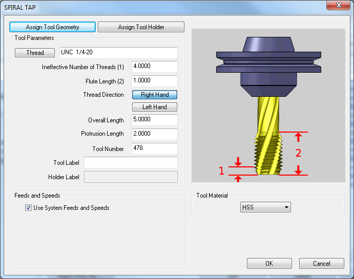
This page will allow you to create new, or modifying existing tools and tool holders. This page will also allow you to assign Tool Numbers and Offsets, as well as Speeds and Feeds and designated materials.

Assign Tool Geometry - hides the tool dialog box to allow you to select geometry from the Workspace to assign as the geometry of the tool.
Assign Tool Holder - brings up the Mill Tool Holder Library which allows you to Add, Delete and Edit Arbors and Holders.
|
|
Use System Feeds and Speeds
![]() Select this check
box to use the system generated feeds and speeds. The system feeds and
speeds are created using a combination of the selected tool material and
the selected stock material for the job. To learn more, view the Stock
Material Library.
Select this check
box to use the system generated feeds and speeds. The system feeds and
speeds are created using a combination of the selected tool material and
the selected stock material for the job. To learn more, view the Stock
Material Library.
![]() Clear this check
box to manually enter custom feeds and speeds directly in the dialog box.
The parameters become available after the check box is cleared. When you
enter values this way, you are defining the default feeds and speeds used
for the this tool when you create a machining feature. To elaborate, the
values entered here are used for the tool when the Use System Feeds and
Speeds check box is selected in the Mill Wizard.
Clear this check
box to manually enter custom feeds and speeds directly in the dialog box.
The parameters become available after the check box is cleared. When you
enter values this way, you are defining the default feeds and speeds used
for the this tool when you create a machining feature. To elaborate, the
values entered here are used for the tool when the Use System Feeds and
Speeds check box is selected in the Mill Wizard.