In this Topic Show
The View functions provide various ways to modify the view in the current graphics area. This topic lists all of the view functions in the order that they appear in the View menu. To learn about each function, click the links listed next.
To access the View functions, do one of the following:
The ON function is used to hide and show the graphics area tabs (or Workbook) at the bottom of the screen.
The Icons function is used to hide or show the icons that are displayed in each graphics area tab at the bottom of the screen.
The Blank function is used to hide selected geometry from view. To perform the function, click Blank, select geometry in the graphics area, and to confirm the selection, press the Spacebar. The geometry is hidden from view. To make the geometry visible again, use Unblank.
TIP: You
can also place geometry on a layer (using the ![]() Layers tab) that can be hidden and
shown.
Layers tab) that can be hidden and
shown.
The Unblank function is used to show geometry that has been hidden using
the Blank function. To perform the function, click Unblank, select the
geometry that you want to show, and to accept the selection, click ![]() OK.
OK.
The Pan function is used to pan or move the current viewing position
in the graphics area. To perform the function, click Pan (the mouse pointer
changes to the pan icon), then click and drag the view to the desired
position, and then release the mouse button. To end the function, click
![]() Cancel (or press Esc).
Cancel (or press Esc).
TIP: You can also hold down Shift and click the middle mouse button to perform panning.
The Rotate function is used to rotate or change the viewing angle (around
the center of the current viewing position) in the graphics area. To perform
the function, click Rotate, and then click and drag the mouse to change
the view. To cancel the function, click ![]() Cancel.
Cancel.
TIP: You can also drag with the middle-mouse button to perform the function.
The Fit All function is used to change the view of the graphics area so that all geometry can be seen. When you click Fit All, the function is performed.
TIP: You can also press F on the keyboard to perform Fit All.
The Zoom Window command is used to drag a window in the graphics area and have the selected area expanded to the full window size. To perform the command, click Zoom Window, drag a window in the graphics area, and then release the mouse to zoom in on the selected area.
TIP: You can also press and hold Ctrl, while dragging a window in the graphics area. When you release the mouse button, the view is changed to the selected area. This eliminates the need to click Zoom Window.
The Zoom Previous command returns to the last view perspective used.
The Zoom In command makes objects in the current graphics area appear closer. This only changes the perspective of the current view.
The Zoom Out command makes objects in the current graphics area appear further away. This only changes the perspective of the current view.
The View presets provide various ways to view the current part in the graphics area. The view options can be selected from the View menu, the View toolbar, the graphics area shortcut menu, or by using the keyboard shortcuts (listed in the menu with each view).
The View Normal function is used to alter the current view to a view
that is in the normal direction of a selected surface. This means that
the viewing plane is parallel to the selected surface. To perform the
function, select View Normal, and select a planar face in the graphics
area. You can also click Active UCS (in the ![]() Data
Entry tab). If you click Active UCS, then the view is updated to the default
view of the active
Data
Entry tab). If you click Active UCS, then the view is updated to the default
view of the active ![]() UCS.
To cancel the view setting, click Cancel.
UCS.
To cancel the view setting, click Cancel.
TIP: If the view is already in the normal direction of the surface that you select, then the view is changed to the opposite of the Normal view.
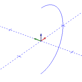
The Section View command is used to create a cross-sectional view of geometry in the graphics area, with the ability to extract wireframe from the view. Section View
The Ortho Projection function is used to change the view in the graphics area between the default perspective view and an orthogonal view. To perform the function, you click Ortho Projection; to return to the default view, click Ortho Projection a second time.
The Antialiasing function smooths the edges of geometry displayed in the graphics area. This is only used to improve the appearance of the geometry in the graphics area, for example, when using Print Screen to create an image.
NOTE: This function creates a significant increase in memory usage by the system. Depending on your system configuration, you may not want to use this option. If the software seems to be operating slowly, turn the function off and see if operation returns to normal.
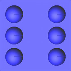
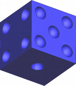
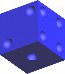
The Shading Smooth function is used to smooth the appearance of solids/surfaces in the graphics area. This is turned on by default. To turn the function off, click Shading Smooth. To return to the default view, click Shading Smooth again.
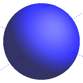
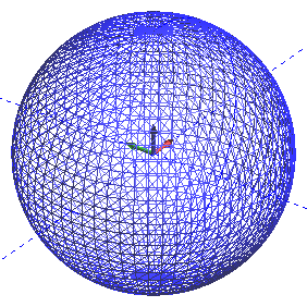
The Polygon Shaded function is the default view used for solid/surface entities. They appear as a shaded solid/surface. The Polygon Lines function is used to change this view to a triangle mesh.
The Polygon Lines function is used to show the triangle mesh of solid/surface entities in the graphics area. When you click Polygon Lines, the view of the solid is updated. To return to the shaded view, click Polygon Shaded.
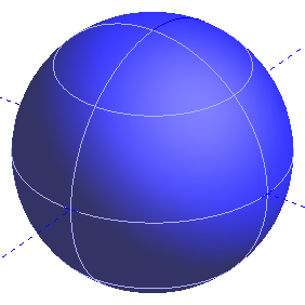
The Wireframe View command shows and hides the interior lines of surfaces and solids.
TIP: You can also press W to turn on and off the Wireframe command.
The Shaded function is used to toggle the view of solids/surfaces, in the graphics area, between a surface view or wireframe view. To perform the function, click Shaded. To return, click Shaded a second time.
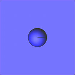
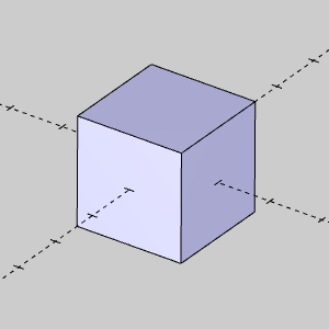
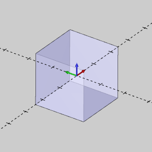
The Transparent function is used to make solids/surfaces in the graphics area appear transparent (or see through). To perform the function, you click Transparent. To return to the default view, click Transparent again.
TIP: You can also press T to turn on and off the transparent view.
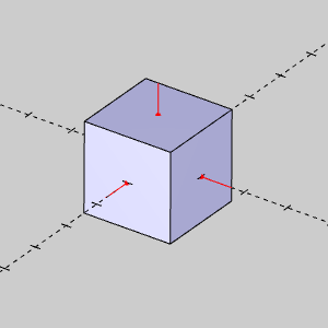
The Surface Normal function is used to show or hide the surface normals of solids/surfaces in the graphics area. This indicates the outward (positive) direction of solids/surfaces. This function is important for creating Multiaxis features. How to Reverse the Surface Normal Direction
The Hide All Images function is used to hide any imported images (in the graphics area) from view. This function is only available in the View menu. To show the images, click Hide All Images a second time. This function is used with BobART.
The Hide All Emboss Model function is used to hide embossed geometry that is created using BobART. This allows you to view any geometry that is hidden by the model so it can be selected for other features. To view the model again, click Hide All Emboss Model a second time.