This topic provides a walk-through example of how to use Extrude Cut. This example is supplemental to the Extrude Cut topic.
A BobCAD file installed with the software can be opened to follow along with this example.
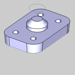
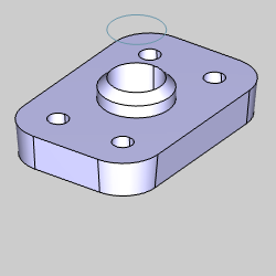
In the example file, Extrude Cut is used to cut a hole through the center of a solid flange.
1 In the File menu, click Open.
2 Navigate to: C:\BobCAD-CAM Data\BobCAD-CAM V**\Examples, and select Extrude Cut Example.bbcd.
3 With Extrude Cut Example.bbcd displaying in the File Name box, click Open.
To open Extrude Cut, do one of the following:
In the Solids menu, click Extrude Cut.
On the Solids toolbar,
click the  icon.
icon.
Right-click anywhere in the Workspace, point to CAD, Solids, and click Extrude Cut.
The parameters display in the  Data Entry tab of the Data-CAM Tree Manager.
When using Extrude Cut, you can select closed wireframe chains or planar surface geometry. For this example, we select a wireframe chain and then explore Dynamic Drawing to define the extrusion direction and distance from the chain.
1 Press
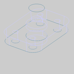
S, or select Shaded
from the View menu.
The Shading is removed from the model.
2 Under
the graphics area, change the value of the  (Snap
Increment) to 0.2500.
(Snap
Increment) to 0.2500.
This allows us to sketch CAD sizes and depths in increments of 0.2500.
3 For this example, we select the geometry first before defining the Data Entry parameters. This way we can create the CAD preview and explore Dynamic Drawing.
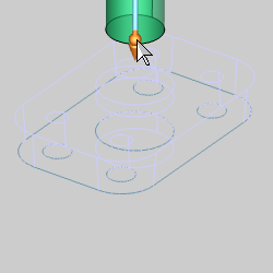
In the graphics area, hover over the circle, as seen in the image below.
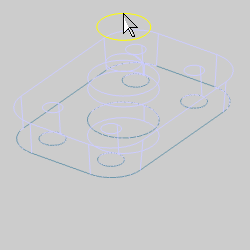
4 Click
the arc to add it to the Selected Geometry
list.
The Preview appears.
NOTE: Notice that by default the circle is extruded one unit in the positive direction. For any Extrude function, you can specify the extrude distance in either or both directions from the selected geometry. You can also apply a Draft Angle to either or both directions.
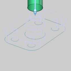
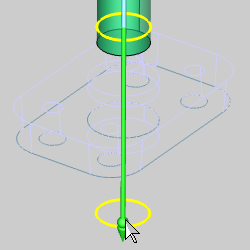
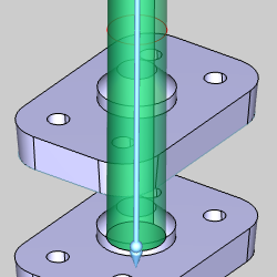
5 To show how Dynamic Drawing works, hover over the sketch handle as seen in the image below.
6 Click
the sketch handle to activate it.
The sketch handle highlights and the preview moves down based on the next
snap increment.
NOTE: When a sketch handle is activated, the CAD preview changes to a wireframe display until you place the sketch handle. Move the handle down and notice it does not move smoothly, but jumps by an incremental amount. This is the snap increment amount that has been set. Notice too, that the Other Direction Distance is updating as the sketch handle is being moved.
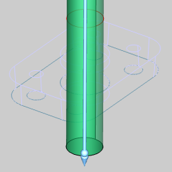
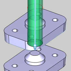
7 Move the sketch handle so that the Other Direction Distance is set to 3.0000.
8 Click
to set the sketch handle.
The Preview updates.
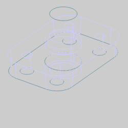
9 To
perform the Extrude Cut, click OK in
the Data Entry Manager.
The Extrude Boss is created in the graphics area and another ![]() Extrude
Cut feature is created in the
Extrude
Cut feature is created in the ![]() CAD
Tree.
CAD
Tree.
10 Press
S, or select Shaded
from the View menu.
The Shading appears on the model.
11 To close the Data Entry Manager, click Cancel.
The process of creating an Extrude Cut is complete. The rest of this example provides some important usage tips.
It is important to understand that any solid body in the file that intersects the extruded shape is included in the Extrude Cut result. This applies to all visible or hidden solids unless they are hidden using the View menu Blank command. Hiding a CAD layer does not exclude the solids on that layer.
1 In
the Layer-UCS-Post Manager, click
the Layers
tab if it isn't already selected.
2 In the Layers Manager, right-click the layer name Flange Copy, and click Show.
If needed, rotate the view to see that the second flange was also cut, even though it was on a hidden CAD layer.
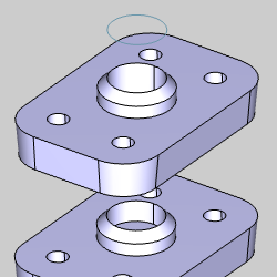
If the second flange was hidden using Blank, it would not have been included in the Extrude Cut.
NOTE: After hiding a solid using Blank in order to exclude it from an Extrude Cut, or Boss and then showing the solid using Unblank, if the CAD Tree is rebuilt, that solid will then be included in the Extrude Cut result. If this creates a problem, you can use Solid Subtract instead of Extrude Cut.
For this example we didn't want to cut the second flange. This problem is easily resolved by editing the Extrude Cut feature.
One CAD feature is added to the CAD Tree each time you perform Extrude Cut. The feature in the CAD Tree provides many tools for editing, suppressing, renaming the feature, and more as explained in the CAD Tree.
After closing the Data Entry Manager, the CAD Tree automatically displays.
You can also click the  CAD Tree tab of the Data-CAM Tree Manager to access the CAD Tree.
1 Notice
the Extrude Cut feature at
the bottom of the CAD Tree.
Right-click Extrude
Cut, and click Edit.
The CAD preview displays, and the Extrude Cut Parameters open in the Data
Entry tab.
2 Under Other Direction, change the Distance value to 2.000, and press Tab to update the preview.
3 To finish editing the feature, click OK.
This concludes the example.