 icon.
icon.This topic provides an example of how to create a Swung surface in BobCAD-CAM. This topic is supplemental to Swung Surface.
A BobCAD file was installed with the software and can be opened to follow along with this example.
1 In the File menu, click Open.
2 Navigate to: C:\BobCAD-CAM Data\BobCAD-CAM V**\Examples, and select Swung Surface Example.bbcd.
3 With Swung Surface Example.bbcd displaying in the File Name box, click Open.
To open the Swung Surface function, do one of the following:
 icon.
icon.
The parameters display in the ![]() Data Entry tab of the Data-CAM Tree Manager.
Data Entry tab of the Data-CAM Tree Manager.
The first step is to select the geometry and create the CAD preview. This way we can modify the Data Entry parameters and get visual feedback of the result before creating it.
Swung Surface requires two chain selections: the Trajectory Curve or path (on the XY plane) and the Profile Curve (on the XZ plane). You can perform chain selection in one of two ways. You can click to set the starting entity of a chain and then hold Shift and click to set the ending entity of the chain, or you can hold Shift and click the end of the last chain entity. For Swung Surface, you can often use the second method.
1 Press and hold Shift and click to chain select the Trajectory Curve on the XY plane. Click near either end of the chain.
Notice that the Trajectory Curve is selected on the XY plane of the Active UCS.
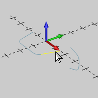
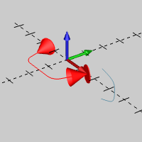
The start and end arrows display to show that the current chain selection is finished.
2 Hold Shift and click to chain select the Profile Curve on the XZ plane. (Click near the upper end of the chain.)
Note that the Profile Curve is selected on the XZ plane of the Active UCS.
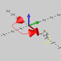
After chain selecting the profile curve, the CAD preview displays in the Workspace.
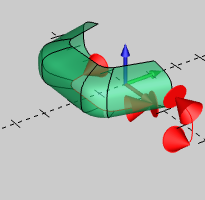
Notice the resulting surface. The profile curve follows the trajectory curve while being revolved around the Z-axis of the Active UCS. (Also, the direction of the profile curve does affect the result when using Follow Trajectory Curve as it defines where the profile starts and ends in relation to the path.)
You also have a choice to create the surface using the location of the selected profile curve.
1 In the Data Entry Manager, click Follow Profile Curve.
The CAD preview updates to reflect the change.
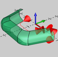
The surface now uses the location of the profile curve to define the trajectory path.
2 To create the surface as shown in the CAD preview, click OK.
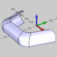
3 The Swung Surface is complete. To close the Data Entry Manager, click Cancel.
After creating a Swung Surface, it is added to the CAD Tree. This allows you to modify the results after creating the surface.
In this part of the example, we move our profile curve to show a few important processes.
1 In
the Data-CAM Tree Manager, click the ![]() CAD
Tree tab.
CAD
Tree tab.
2 Notice the Swung Surface feature in the CAD Tree. You can click the feature name to highlight the surface in the Workspace.
A shortcut menu is provided to allow you to modify the feature.
3 Right-click
 Swung Surface,
and click Suppress/Unsuppress in
the shortcut menu.
We are temporarily suppressing the feature to make it easier to modify the wireframe input.
4 In the Utilities menu, click Translate.
5 In the Data Entry Manager below End, set the Z value to 2.000.
6 Click to select the profile curve.
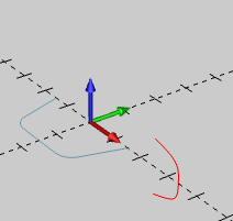
7 To confirm the selection, press Spacebar.
8 To move the curve, in the Data Entry Manager, click OK.
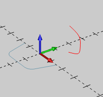
9 To close the function, click Cancel.
1 In
the ![]() CAD Tree,
right-click
CAD Tree,
right-click  Swung
Surface, and click Suppress/Unsuppress.
The surface returns to the Workspace.
2 Right-click Swung Surface, and click Rebuild.
We are rebuilding the feature because we modified the input geometry.
Notice that because we used Follow Profile Curve, the surface updates to the modified profile geometry.
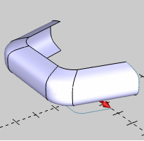
Notice that Follow Profile Curve uses the Z-axis location of the profile curve to create the surface.
3 Right-click Swung Surface, and click Edit Parameters.
This option allows you to update the Data Entry parameters for the function without the need to reassign geometry.
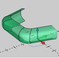
The function opens with the CAD preview displayed as the geometry is automatically pre-selected.
4 In the Data Entry Manager, click Follow Trajectory Curve.
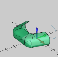
5 To update the changes to the surface, click OK.
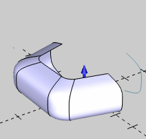
The profile curve now follows the location of the trajectory curve.
As a final note for Swung Surface, the location of the Z-axis of the Active UCS is an important part of the resulting surface as it is the revolution axis for the surface along the path.
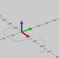
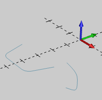
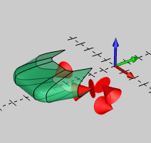
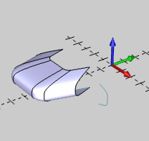
The following images show the result of the same wireframe geometry used in the previous example, but created from a different UCS. Note that the following example shows more of a creative use of Swung Surface as it results in scaling or stretching of the surface in the XY plane.
This concludes the example.