How to Create a Wire EDM Coreless Operation
Introduction
In this example, we examine how to create a Wire EDM coreless operation. The main points of this tutorial include the settings that are required to create a coreless operation, the use of a start hole diameter, the difference between the Lead-in types, and benefit of using the Select Point lead-in. Setting up the software to output a start hole program is also explained.
Machining Scenario
In this example, a Wire EDM Job is created, stock is defined, and the machine setup (machining origin) is placed at the bottom and center of the part.
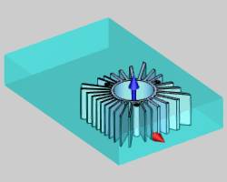
Part 1) Settings Needed to Create a Coreless Operation
In this part of the example, we create the basic coreless operation while learning the required settings.
-
In the CAM Tree, right-click
 Machine
Setup, and click 2 Axis Inside.
The Coreless operation is only available for the 2 Axis Inside Wire EDM feature type. -
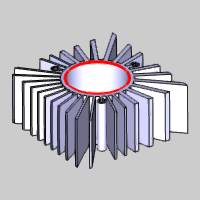
In the Geometry Selection page of the Wire 2 Axis Wizard, we assign a closed inside profile as shown next.
-
In the Feature page of the wizard, there are two required settings.
In the Glue Stop Options group, select No Glue Stop.
In the Taper Settings group, select None. -
In the Machining Strategy, Strategy 2 is selected because it contains only one Rough Cut operation. (You can have a Skim Cut operation after the coreless Rough Cut operation, but we create only the Rough Cut operation to simplify the tutorial.)
-
In the Parameters page of the 2 Axis Rough Cut operation, the Pattern is set to Coreless.
When you select Coreless, the Stepover % becomes available. In this example, the default stepover of 50.00 percent of the wire diameter is used. -
Before defining the Leads, we Compute the wirepath to create the coreless operation.
With just a few pertinent settings, the coreless operation is created.
Note: The Coreless option is only available in the Parameters page of the Rough Cut operation for the 2 Axis Inside feature type. Also, in the Feature settings, the Glue Stop Options, No Glue Stop, and Taper Settings, None, must be selected to enable the Coreless option.
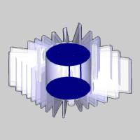
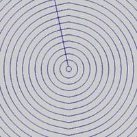
In the previous image, you can see that the coreless (pocketing) wirepath fills the entire feature. This is a result of the default Start Hole diameter of zero for the feature.
Part 2) Set the Start Hole Diameter
For coreless operations, you usually have a start hole in order to thread the wire before starting the operation. When you define the Start Hole Diameter, no wirepath is created within the start hole.
-
To edit the feature, in the CAM Tree, right-click
 Feature EDM 2X Inside, and click Edit.
 -
On the left side of the wizard, click Leads.
-
In the Entry group, set the Start Hole Diameter to the appropriate value to remove the coreless wirepath from this area.
-
Compute the wirepath to update the change to the feature.

Part 3) Understanding the Lead-in or Coreless Thread Point
When a Rough Cut operation is set to Coreless, the Lead-in group of the Leads page for the operation changes from Lead-in to Coreless Thread Point, a specialized lead-in type for the coreless operation. There are two options: Automatic or Select Point. It is important to understand how each option works so you can properly define the feature.
For the Automatic type, the software continually offsets the feature (inward) until the entire pocket contains a wirepath. The start of the wirepath is then just outside of the inner-most offset, which is not necessarily the exact center of the feature. The Start Hole location is then determined by the start of the wirepath.
For the Select Point type, you gain complete control of the Start Hole location. You can either type coordinate values, or select a point from the Workspace. With this lead-in type, the start of the wirepath is always placed exactly at the center of the start hole.
The following images show the difference in the start location of the wirepath when using Automatic (first image) and Select Point (second image). (The Start Hole Diameter was set to zero to better show the center of the feature for comparison).
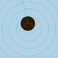
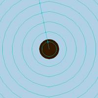
The Coreless Thread Point is selected in the Leads page of the wizard. When you change the Type from Automatic to Select Point, the First Point X, First Point Y, and Select Point parameters display. You can either type values in the First Point X and First Point Y boxes, or click Select Point and select a point from the workspace.
When using either Coreless Thread Point option, Automatic or Select Point, you can use the Hole Post options to output a separate .nc program with the hole locations for the feature.
Part 4) Output the Start Hole Program
When creating a coreless operation, you can always check the code to confirm the start of the wirepath. In addition to the standard program output, you can also output a Start Hole program with only the drill hole locations for the job. This section explains how to setup your system to output a Start Hole program.
Default Hole Post Settings
First we set the default posting settings so that all new files created use the same settings. If you want to change these parameters for the job only, then you can skip to Job Hole Post Settings.
-
In the CAM Tree of the Data-CAM Tree Manager, right-click
 CAM Defaults, and click Current Settings.
 -
In the Machine Parameters, select your wire machine next to Make.
When you select a wire machine, the Current Settings update to the appropriate pages for Wire EDM. -
Click EDM Posting, and then click Hole Post.
In the Open dialog box, select a hole post processor with an .HPST extension, and click Open. -
On the left side of the Current Settings, click EDM Setup.
In the Output group, click to select the Output Start Hole Program check box. -
At the bottom of the Current Settings, click OK.
By making the changes as described, all new jobs that are created using the selected machine will output a start hole program with the specified hole post processor.
Tip: These changes made in the Current Settings Default do not affect the current job. To update the current job settings (or if you do not want to use these settings as the default), use the following steps.
Job Hole Post Settings
-
In the CAM Tree of an existing job, right-click
 Wire
EDM Job, and click Current Settings.
 -
In the Machine Parameters, next to Make, confirm that the appropriate machine is selected. (You should already have your machine selected for the job.)
-
Repeat steps 3-5 as explained in Default Hole Post Settings.
By making the changes as described, the current job now outputs a Start Hole program as well as the regular program code. (These settings do not affect the default settings for new jobs.)
Locating Both NC Programs
If you right-click Wire EDM Job, and click Post (not Post and Save As), the default location for .nc files is: C:\BobCAD-CAM Data\**Current Version**\NC\Wire EDM
In this location, two .nc files are created for the program: Filename.nc and FilenameHoles.nc
If you use Post and Save As instead, then the files are saved with the name and location that you specify. (The Start Hole program uses the same name with the word Holes appended to the filename.)
When you examine the code that is output in the Start Hole program, you can see that with the Automatic Coreless Thread Point, the output is not at the exact center of the feature. When changing to the Select Point type, the start hole is exactly as specified.
This concludes the tutorial.
