The Wire EDM Job
Introduction
This topic will explain where to create a Wire EDM Job from, will explain the Wire EDM Job, and all the items found in it. This topic will also provide links to related topics.
The Wire EDM Job
The Wire EDM Job in the CAM Tree provides the tools needed to define job settings, machine and post processor selection, stock, stock material, toolpath patterns, and Wire EDM features.
Navigation
To create a Wire EDM Job, use one of the following two options:
- In the CAM
Tree, right-click
 CAM Defaults, and click New Job.
- In the CAM Job group, of the CAM ribbon, click
 New CAM Job.
 - In the quick access toolbar, of the CAM Tree Manager, click
 New CAM Job.
The Machining Job dialog displays.- Click Wire
EDM, and click OK to
add the job to the CAM Tree.
You can also click Stock Wizard to open the Stock Wizard and define the stock and machine setup for the job.
- Click Wire
EDM, and click OK to
add the job to the CAM Tree.
The Wire EDM Job in the CAM Tree
The following items are added to the CAM Tree when you create a Wire EDM job.
![]() Wire EDM Job
Wire EDM Job
![]()
![]() System Default
System Default
![]()
![]() Machine
Machine
![]()
![]()
![]() Post Processor
Post Processor
![]()
![]() Workpiece
Workpiece
![]()
![]() Stock
Stock
![]()
![]()
![]() Stock
Material
Stock
Material
![]()
![]() Machine Setup
Machine Setup
All of the job items in the tree contain a right-click shortcut menu that is used to access the commands as explained next.
The Shortcut Menus
Job Settings, Commands, and Setup Sheets
Right-click Wire EDM Job to open a shortcut menu with the following commands.
![]() Wire EDM Job
Wire EDM Job
-
Current Settings - opens the Current Settings Job dialog box for you to change various machine and posting settings for the job only.
-
Machining Order - opens the Machining Order dialog box for you to define the posting order and optimization.
-
Post - creates the NC program and displays it in the
 Posting tab (of the
Layer-UCS-Post Manager). You can view the posted program, but
you can't edit it in this location. Right-click anywhere in the
Posting window to access another shortcut menu, or use Post &
Save As.
 -
Post & Save As - creates and displays the NC program, but first opens the Save As dialog box for you to name and save the file. You can use the default location, or select your own location.
-
Generate Setup Sheet - opens the Setup Sheet dialog box for you to select a template to format the output of the setup sheet and define what information is included. Select a Template, and click OK. The setup sheet is created and displayed in a browser showing all of the applicable information for the current job.
-
Generate Setup Sheet & Save As - opens the Setup Sheet dialog box for you to select a template to format the output of the setup sheet and define what information is included. Select a Template, and click OK. The Save As dialog box is displayed for you to select a location in which all of the setup sheet information is stored. Select a location and name the .xml file. When you click OK, a folder is created with all of the same information of the selected template, and the .xml file, in the specified location. The setup sheet is then displayed in a browser showing all of the applicable information for the current job.
Tip: When the Setup Sheet information displays, you can use the File - Save As command of the browser to save the file to another format or for later use. You can also print the setup sheet using the File - Print commands of the browser.
-
Simulation - opens the simulation window for you to view any computed feature operations set to Post Yes. To learn more, view Getting Started with Simulation.
- Update
All Geometries - Updates all geometry associated in the
CAM Tree.
- Compute
All Toolpath - computes all feature operations in the job.
-
Post Yes/No - toggles whether or not all feature operations in the job are output in the posted program.
-
Blank/Unblank All - toggles the visibility status of the stock and all operations in the job to hide or show. Note that you can then click any CAM Tree icon that contains a preview to show the preview of that item in the workspace until you click another location to change the focus.
-
Edit Cutting Conditions - opens the Edit Cutting Conditions Database dialog box for you to modify the cutting conditions parameters, which allows you to modify and save the database information.
-
Search Cutting Conditions - (shown for Sodick AQ machines only) opens the Sodick Cutting Conditions Search dialog box for you to search the Sodick Cutting Conditions as a reference that you can use when setting values in the Cutting Conditions dialog box of the Wire EDM Wizard.
- Save as Job Template - saves the entire job to be loaded as a template for later jobs. See The Job from Template topic for more information.
-
Delete - deletes the entire job and all items from the CAM Tree.
-
Collapse Items - collapses the child items of the Wire EDM Job folder. This is the same as clicking the minus sign (
 )
next to all child items of Wire EDM Job.
 -
Expand Items - expands the child items of the Wire EDM Job folder. This is the same as clicking the plus sign (
 )
next to all child items of Wire EDM Job.
- Rename - allows you to rename the job.
System Default
The System Defaults allow you to alter the default values for all features and operations. To learn more, see The Default Parameter Templates topic.
![]() System Default
System Default
- Edit - opens the Parameter Template Selection dialog to allow you to select a specific template from the available saved templates.
Machine Selection
Right-click Machine to open a shortcut menu with the following command.
![]() Machine
Machine
- Edit - opens the Machine Selection dialog box for you to select a machine for the job. This is a quick-change dialog box that is provided for you to change the machine without the need to open the Current Settings Job dialog box. Next to Make, click the arrow, and select a machine from the list. To change the machine and close the dialog box, click OK.
Post Processor Selection
Right-click Post Processor to open a shortcut menu with the following command.
![]() Post Processor
Post Processor
- Edit - opens the Set Post Processor dialog for you to change the post processor that is used to generate the NC Program. This is a quick-change dialog box that is provided for you to change the post processor without the need to open the Current Settings Job dialog. Click Select to display the Open dialog box, and select a .EDMPst file. To update the post processor and close the dialog, click OK. Click OK again to close the Set Post Processor dialog.
Assigning a Workpiece
The Workpiece item in the CAM Tree allows you to assign the geometry that displays in the simulation window as the workpiece (final part). When you assign a workpiece, only the assigned geometry is passed to simulation regardless of how many models are visible in the Workspace. The workpiece can be assigned during the job setup or by using the CAM Tree.
Right-click Workpiece to access a shortcut menu with the following commands.
![]() Workpiece
Workpiece
- Re/Select
- enables selection mode for you to assign workpiece geometry
or to modify the current assignment. After assigning or modifying
the selection, click OK (
 ).
). -
Remove - eliminates the geometry assignment for the workpiece. If you do not assign workpiece geometry, all visible models in the workspace are passed to simulation.
Stock Creation and Modification
Right-click Stock to open a shortcut menu with the following commands.
![]() Stock
Stock
- Stock
Wizard - opens the Stock
Wizard for you to define the stock for the job.
- Color
- opens the Color dialog box for you to change the color of the
displayed stock geometry. Select a color, or define a custom color,
and click OK to close the dialog box and update the color.
- Transparency
- opens the Stock
Transparency dialog box for you to modify the transparency
of the stock geometry. Higher settings make the stock more transparent
or see-through. After adjusting the transparency level, you can
set the system default stock transparency by clicking Set Default.
- Blank - toggles the visibility of the stock in the workspace. This hides or shows the stock based on its current condition. Note that you can click the Stock item in the tree to temporarily display the (hidden) stock geometry, until you click another tree item.
Material and Wire Diameter Selection
Right-click Material (the current material name, such as Aluminum) to open a shortcut menu with the following command.
![]() Material
Material
- Edit - opens the Material and Wire Diameter Selection dialog box for you to select the material and wire diameter for the job. This is used to define many of the Cutting Conditions (such as power settings) in the wizards. Select the desired Material and Wire Diameter, and click OK to update the material and close the dialog box.
Important: The materials that are available in the Material and Wire Diameter Selection dialog box are determined by the information available in the Cutting Conditions Database file that is selected for the current machine. If there are no materials available, then you are not connected to a Cutting Conditions Database.
Machine Setup Modification and Feature Creation
Right-click Machine Setup to open a shortcut menu with the following commands. These include commands for modifying the machine setup, adding Wire EDM features, calculating toolpaths, setting posting status, and more.
![]() Machine Setup
Machine Setup
- Edit -opens
the Machine
Setupdialog box in the Data Entry Manager for you
to modify the current machining origin, and work offset value.
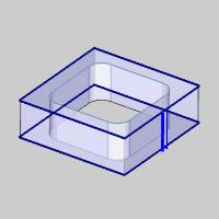
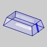
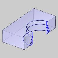
- 2 Axis Inside - opens the 2 Axis Wire EDM Wizard for you to create a 2 Axis EDM Inside feature. This handles closed internal (die) features with or without constant taper. The available operations are: Rough Cut, Skim Cut, and Tab Cut.
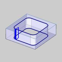
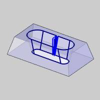
The 2 Axis Inside feature also provides the ability to create Land and Taper as shown next.
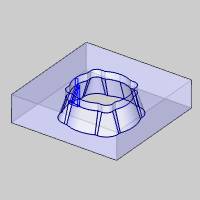
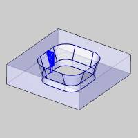
- 2 Axis Outside - opens the 2 Axis Wire EDM Wizard for you to create a 2 Axis EDM Outside feature. This handles closed external (punch) features with or without constant taper. The available operations are: Rough Cut, Skim Cut, and Tab Cut.
- 2 Axis Open- opens the 2 Axis Wire EDM Wizard for you to create a 2 Axis EDM Open feature. This handles open features with or without constant taper. The available operations are: Rough Cut, Skim Cut, and Tab Cut.
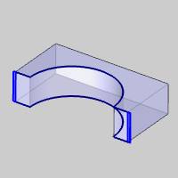
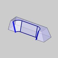
The 2 Axis Open feature also provides the ability to create Land and Taper as shown next.
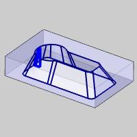
- 4 Axis Inside- opens the 4 Axis Wire EDM Wizard for you to create a 4 Axis EDM Inside feature. This handles closed internal (die) features with the available operations: Rough Cut, Skim Cut, and Tab Cut.
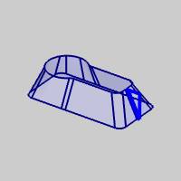
- 4 Axis Outside - opens the 4 Axis Wire EDM Wizard for you to create a 4 Axis EDM Outside feature. This handles closed external (punch) features with the available operations: Rough Cut, Skim Cut, and Tab Cut.
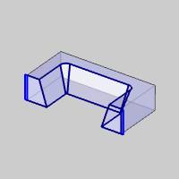
- 4 Axis Open- opens the 4 Axis Wire EDM Wizard for you to create a 4 Axis EDM Open feature. This handles open features with the available operations: Rough Cut, Skim Cut, and Tab Cut.
- Update All Geometries
- Updates all geometry associated in the CAM Tree.
- Compute All Toolpath - computes the operations of all features contained in the
Machine Setup.
- Add Group - adds
a folder to your CAM Tree. Drag and drop features into the folder
to save space in the CAM Tree and have the control to set Add
Toolpath Pattern, Post All Yes/No and Blank/Unblank Toolpath options
on all features inside of the folder at one time.
- Add Toolpath Pattern
- adds a Toolpath
Pattern to the selected machine setup. When added from this
location, the defined pattern is applied to all of the features
in the machine setup.
- Load Feature - allows
you to locate and add a previously saved feature to the tree.
- Paste Feature - is
used to paste a copied feature to the Machine Setup after the
last feature.
- Delete All Features
- removes all features from the Machine Setup.
- Post All Yes/No - sets
all toolpaths in the Machine Setup to post or not post in the
NC program.
- Blank/Unblank Toolpath
- allows you to hide or show all toolpaths in the Machine Setup.
- Collapse Items - collapses
the child items of the Machine Setup. This is the same as clicking
the minus sign (
 )
next to all child items.
 - Expand
Items - expands the child items of the Machine Setup. This
is the same as clicking the plus sign (
 ) next
to all child items.
- Rename - enables editing of the Machine Setup name in the CAM Tree. Type the new name for the setup.
Feature Modification
To learn about the feature that is added to the job after finishing the wizard, view Wire EDM Features in the CAM Tree.
