


 Cylinder
Introduction
This topic will explain the Cylinder function, will explain whereto find the function, and explain the options found in it.This topicwill also give a brief description of Dynamic Drawing, the Snap Incrementfunction, explain creation with quick steps, and provide links to relatedtopics.
The Cylinder Function
The Cylinder function creates solid cylinder primitives.Dynamic Drawing allows you to use sketch handles to modify the locationand dimensions of the solid, which can also be defined using data entry.The benefit of Dynamic Drawing is that both methods can be utilized atany time during creation.You can use the sketch handles to roughly definethe solid geometry and then use data entry to accurately update the locationand dimensions as needed.

Dynamic Drawing
This function supports Dynamic Drawing which allows you to use a combination of sketching and data entry to create the entities. Prior to confirming the desired result in the function, an adjustable preview is visible. These previews can be modified using the sketch handles, data entry, or a combination of both. The benefit of Dynamic Drawing is that you can quickly place and adjust the size to get the approximate result, and then use data entry to update to the exact dimensions, and coordinate values as needed.
|
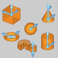
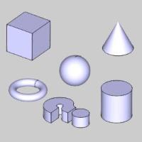
Preview with Sketch Handles |
Final Entities |
|
|
In the images above, we see the preview of entities which can be adjust with sketch handles, followed by those same entities after they are finalized.
Snap Increment
This function support the use of the snap increment when selecting the location of the entities. The snap increment allows you to get precise results when using mouse selection and helps to reduce data entry modifications.
To learn more, view Snap Increment.
Navigation
To open Cylinder:
- In the Primitives group, of the Create 3D tab, click
 Cylinder.
The parameters display in theData Entry Manager.
The Data Entry Parameters
These value can be set using either data entry or thesketch handle.The snap incrementapplies when using the sketch handle.
Parameters
-
Diameter - sets the width of the cylinder from either side of its circumference.
- Radius - sets the width of the cylinder from its center to the outer edge of its circumference.
- Height - sets the totalheight of the cylinder.
Origin
The origin determines the coordinate location using the XYZ coordinates of the Active UCS. You can set the origin location using either data entry or the origin sketch handle. The snap increment applies when using the origin handle.
- X - is the X Axis location of the entity origin.
- Y - is the Y Axis location of the entity origin.
- Z - is the Z Axis location of the entity origin.
Important: The XYZ coordinates are in reference to the Active UCS, or user coordinate system.
- OK - confirms the current settings to create the entity as shown in the CAD preview.
- Cancel - closes the function.
Quick Steps - Cylinder
-
Open the function and define all Data Entryparameters for the entity.
-
Use any combination of data entry or sketchhandles to determine the size and location of the entity.
You can modify the snap incrementvalue or turn it off if you are using sketch handles.
To learn more about Dynamic Drawing, view DynamicDrawing for Solids. -
To create the entity as shown in the CADpreview, in the Data Entrytab, click OK.
To create another entity, repeat steps 2 and 3. -
To close the function when you are finished,click Cancel.
The feature is added to the CAD Tree.