


Stock Definition
Introduction
The purpose of this topic to explain all the options found in the Stock Definition dialog, and will provide links to related topics.
The Stock Definition dialog
The Stock Definition dialog will allow you to define the shape, size and orientation of the stock.
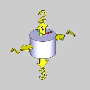
Important: When the Stock Definition dialog box is open,
a ![]() coordinate system gnomon displays to show the stock
Origin, which is located at the top and center of the stock. The stock
origin is only used as
the reference when changing the stock size and orientation, when applicable.
The stock origin is not
related to the machining origin in the Machine Setup.
coordinate system gnomon displays to show the stock
Origin, which is located at the top and center of the stock. The stock
origin is only used as
the reference when changing the stock size and orientation, when applicable.
The stock origin is not
related to the machining origin in the Machine Setup.
 Stock Type
The first step is to define the overall shape of the stock by selecting the Stock Type. All definitions are explained in this topic. To jump to a particular stock types definition, click the associated icon in the table below.
|
Rectangle |
Cylinder |
Wireframe |
Solid |
STL |
Revolve |
|
|
|
|
|
|
|
 Rectangle
Creates a cubic stock.
Creating Rectangular Stock Example
Size
Geometry Options
-
 Geometry from Graphics Area - automatically sets
the stock size using all geometry that is currently in the graphics
area. If solid and wireframe geometry exist, only the solid is used
to create the bounding box.
Geometry from Graphics Area - automatically sets
the stock size using all geometry that is currently in the graphics
area. If solid and wireframe geometry exist, only the solid is used
to create the bounding box. -
 Pick - is used to manually select geometry to
define the bounding box. To enable selection mode, click Pick Geometry. Select the appropriate geometry
from the graphics area, and
then click
Pick - is used to manually select geometry to
define the bounding box. To enable selection mode, click Pick Geometry. Select the appropriate geometry
from the graphics area, and
then click  OK.
OK.
Selected
Geometry - lists all the entities currently chosen to set
the bounds of the stock. This list box only appears when the Pick method is selected for the Geometry Options.
|
|
|
| The list will display all entities currently selected for the function. | |
 (Delete All)
- removes all entities from the Selected Geometry list.
(Delete All)
- removes all entities from the Selected Geometry list.
-
Calculate Stock - is used to confirm the geometry selection and create the stock.
Dimension / Offset
This group allows you to enter, or adjust the X,Y, and Z dimensions of the stock, as well as add offsets in the positive and negative direction of each axis.
| X | Y | Z | |
| Dim | Lists the distance in the X axis. | Lists the distance in the Y axis. | Lists the distance in the Z axis. |
| Offset + | Allows for an offset in the X positive direction. | Allows for an offset in the Y positive direction. | Allows for an offset in the Z positive direction. |
| Offset - | Allows for an offset in the X negative direction. | Allows for an offset in the Y negative direction. | Allows for an offset in the Z negative direction. |
Stock Orientation
This group defines where the stock is located in the graphics area and how the stock is oriented. When the stock geometry is defined, the stock origin is automatically placed at the top and center of the stock.
Coordinate System
Origin - is used to select geometry in the graphics area as the origin.
|
|
|
| This list box will show the entity currently selected for the function. | |
-
X - determines the position along the X-axis of the WCS.
-
Y - determines the position along the Y-axis of the WCS.
-
Z - determines the position along the Z-axis of the WCS.
X Direction - this allows you to select geometry that defines the direction for the X Axis. The last geometry selected will show in the list.
|
|
|
| This list box will show the entity currently selected for the function. | |
Y Direction - this allows you to select geometry that defines the direction for the Y Axis. The last geometry selected will show in the list.
|
|
|
| This list box will show the entity currently selected for the function. | |
Z Direction - this allows you to select geometry that defines the direction for the Z Axis. The last geometry selected will show in the list.
|
|
|
| This list box will show the entity currently selected for the function. | |
Important: When geometry is selected to orient a particular axis, that geometry is saved in the list. If new geometry is selected for another axis that conflicts with the geometry assigned for another axis, the geometry selected last will take precedence.

Creates a cylindrical stock.
Creating Cylindrical Stock Example
Size
Bounding Options
-
Bounding Box - sets the stock by using the extents
of the selected Geometry Option
to create a bounding box that will center the stock. The diameter
of the stock is then equal to the longest side of the rectangular
bounding box.
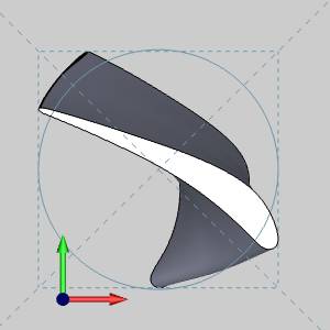
Warning: While the default Bounding Box option works fine in most cases, the image above shows a scenario in which it fails to enclose all of the geometry in the cylindrical stock. The Bounding Box is shown with dotted lines. Notice that the Bounding Box itself encloses the geometry, while the arc that is created fails to.
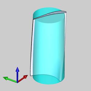
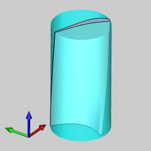
-
Bounding Cylinder - uses an algorithm to
calculate the smallest possible cylinder to enclose the geometry selected
with the Geometry Option to
create stock.

Geometry Options
-
Geometry from Graphics Area - automatically sets
the stock size using all geometry that is currently in the graphics
area. If solid and wireframe geometry exist, only the solid is used
to create the bounding box.
-
Pick - is used to manually select geometry to
define the bounding box. To enable selection mode, click Pick Geometry. Select the appropriate geometry
from the graphics area, and
then click OK.
Selected
Geometry - lists all the entities currently chosen to set
the bounds of the stock. This list box only appears when the Pick method is selected for the Geometry Options.
|
|
|
| The list will display all entities currently selected for the function. | |
-
Calculate Stock - is used to confirm the geometry selection and create the stock.
Dimension / Offset
This group will allow you to set, or modify the diameter and height of the stock.
-
Diameter - sets the width of the cylindrical stock.
-
Height - sets the extrusion length of the cylindrical stock.
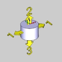
Offset
This group will allow you to set, or modify the offsets of the above diameter and height of the stock.
-
Diameter - (1) adds an offset to the existing diameter.
-
Start Face - (2) adds an offset to the face in the positive direction.
-
End Face - (3) adds an offset to the face in the negative direction.
Stock Orientation
This group defines where the stock is located in the graphics area. When the stock geometry is defined, the stock origin is automatically placed at the top and center of the stock.
Extrusion Direction - sets the initial axis around which the cylindrical stock is revolved.
Coordinate System
Origin - is used to select geometry in the graphics area as the origin.
|
|
|
| This list box will show the entity currently selected for the function. | |
-
X - determines the position along the X-axis of the WCS.
-
Y - determines the position along the Y-axis of the WCS.
-
Z - determines the position along the Z-axis of the WCS.
X Direction - this allows you to select geometry that defines the direction for the X Axis. The last geometry selected will show in the list.
|
|
|
| This list box will show the entity currently selected for the function. | |
Y Direction - this allows you to select geometry that defines the direction for the Y Axis. The last geometry selected will show in the list.
|
|
|
| This list box will show the entity currently selected for the function. | |
Z Direction - this allows you to select geometry that defines the direction for the Z Axis. The last geometry selected will show in the list.
|
|
|
| This list box will show the entity currently selected for the function. | |
Important: When geometry is selected to orient a particular axis, that geometry is saved in the list. If new geometry is selected for another axis that conflicts with the geometry assigned for another axis, the geometry selected last will take precedence.
 Wireframe
Creates a custom shaped stock by extruding selected 2D geometry.
Creating Wireframe Stock Example
Size
Selected
Geometry - lists all the entities currently chosen to set the
bounds of the stock.
|
|
|
| The list will display all entities currently selected for the function. | |
- Calculate Stock - is used to confirm the geometry selection and create the stock.
Top of Stock- is the top of the stock from the WCS (or world coordinate system at X0Z0Y0). You can type a value in the Top of Stock box, or you can click Pick to enable selection mode and select geometry from the graphics area to define the Top of Stock value.
Top - allows you to enter a value to define the top of stock. This also lists the value of the point selected when the list box is used to select geometry from the graphics area to define the top of stock.
|
|
|
| This list box will show the entity currently selected for the function. | |
-
Height - defines the height of the extruded stock from the Top of Stock value.
Stock Orientation
-
Extrusion Direction - sets the initial axis direction in which the wireframe stock is extruded from the selected entities.
Coordinate System
X Direction - this allows you to select geometry that defines the direction for the X Axis. The last geometry selected will show in the list.
|
|
|
| This list box will show the entity currently selected for the function. | |
Y Direction - this allows you to select geometry that defines the direction for the Y Axis. The last geometry selected will show in the list.
|
|
|
| This list box will show the entity currently selected for the function. | |
Z Direction - this allows you to select geometry that defines the direction for the Z Axis. The last geometry selected will show in the list.
|
|
|
| This list box will show the entity currently selected for the function. | |
Important: When geometry is selected to orient a particular axis, that geometry is saved in the list. If new geometry is selected for another axis that conflicts with the geometry assigned for another axis, the geometry selected last will take precedence.
 Solid
Model
Solid
Model
Creates stock from a solid body in the graphics area. Once geometry has been added to the Selected Geometry list, click Calculate Stock. To view stock, hide the solid body selected for the stock.
Create Stock from a Solid Example
Solid Body
Selected
Geometry - lists all the entities currently chosen to set the
bounds of the stock.
|
|
|
| The list will display all entities currently selected for the function. | |
-
Calculate Stock - is used to confirm the geometry selection and create the stock.
 STL
STL
Creates stock from an .STL file.
Create Stock from an STL Example
File Name
Lists the file that was selected with the Browse button to act as stock.
-
Browse - displays the Open dialog box for you to locate and open an .stl file which is used to create the stock geometry. There is an informational display to show the file name of the file currently in use.
STL File Unit
When the dialog opens you will be able to select the unit type in which the .stl file was created.
-
MM - sets the units read from the .stl file as
millimeter.
-
Inch - sets the units read from the .stl file
as inch.
 Revolve
Creates custom stock by revolving sketch geometry.
The revolve stock uses a wireframe profile that is revolved around the Z-axis of the stock origin coordinate system (which defaults to the Z-axis of the WCS). The parameters that display for this stock type are explained next.
Size
The size of custom stock is defined by revolving sketch geometry that you have already created. After assigning the coordinate system for the stock geometry, click in the box, select the geometry to revolve, and click Calculate to create the stock preview in the graphics area.
Selected
Geometry - lists all the entities currently chosen to set the
bounds of the stock.
|
|
|
| The list will display all entities currently selected for the function. | |
-
Calculate Stock - is used to confirm the geometry selection and create the stock.
Note: The following values can be altered after selecting geometry and clicking Calculate. When you change these values, the stock preview is not updated in the graphics area, but the values are saved and automatically loaded in the Feature parameters of the wizard.
Axis
-
 Pick Axis - the axis will be defined manually, with an existing axis, or a defined vector.
  Pick Axis - the axis will be defined by selecting a line, or surface edge.
The following parameters vary depending on the Pick Axis option that is chosen:
![]() Pick Axis
Pick Axis
- Along X Axis - sets the X axis as the axis to revolve around.
- Along Y Axis - sets the Y axis as the axis to revolve around.
- Along Z Axis - sets the Z axis as the axis to revolve around.
- Customized Axis - allows for a custom axis to used for the axis to revolve around.
![]() Pick Axis
Pick Axis
Rotation Axis
|
|
|
| The list box will list the entity currently selected for the function. | |
Note: The direction defines the vector of the rotation. The direction values are always visible, but can only be edited when Pick Axis is not selected, and the Customized Axis option is chosen. When it is, type in the desired values in the X, Y, Z boxes to define the direction from the Origin Point.
- Origin X - sets the X value for the center of rotation.
- Origin Y - sets the Y value for the center of rotation.
- Origin Z - sets the Z value for the center of rotation.
- Direction X - lists the x value for the vector of the rotational axis.
- Direction Y - lists the y value for the vector of the rotational axis.
- Direction Z - lists the z value for the vector of the rotational axis.
Once the Stock Orientation is defined, click
![]()
Related Topics
The Stock Wizard and Machine Setup Tutorials
Next Topic
After setting
the stock size in the Stock Definition, click ![]()