


Mill Turn Example 1
Introduction
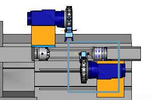
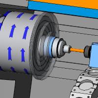
This tutorial walks you through creating a Mill Turn job to completely machine an example part on the BC 2T 2S mill-turn machine as shown in the MillTurn Tutorials topic. This is a two turret, two spindle configuration with live-tooling and Y-axis machining capabilities on the upper turret. In addition to understanding the machine for which we are programming, it is also important to know the naming convention used for the submachines(work zones) as follows.
BC 2T 2S Mill Turn Machine
This tutorial uses the BC 2T 2S Mill Turn machine.
BC 2T 2S Submachine Naming
The submachine naming used for the BC 2T 2S is as follows.
|
UT_MS= Upper Turret, Main Spindle |
UT_SS= Upper Turret, Sub Spindle |
|
|
|
LT_MS= Lower Turret, Main Spindle |
LT_SS= Lower Turret, Sub Spindle |
|
|
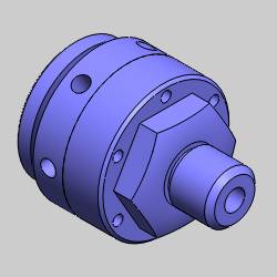
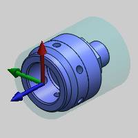
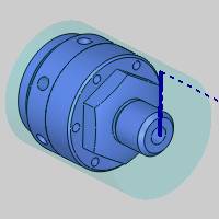
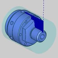
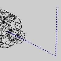
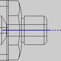
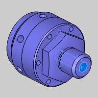
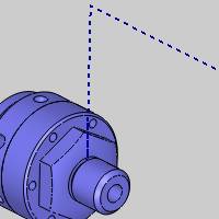
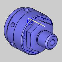
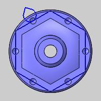
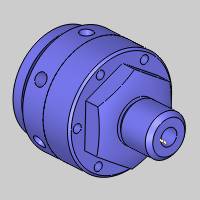
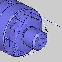
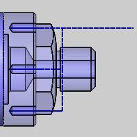
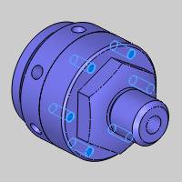
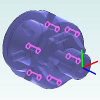
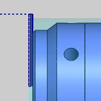
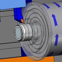
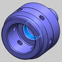
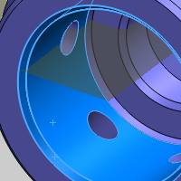
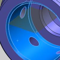
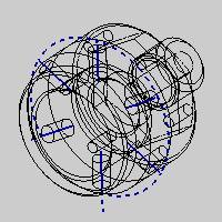
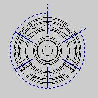
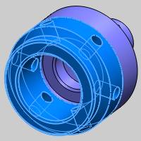
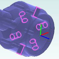
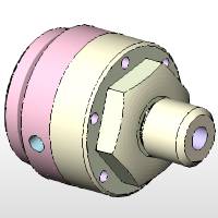
Example Part
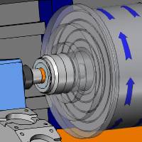
The following images show our example part. For this tutorial, we machinethe part using stock that is already cut to length. For this reason, we create our features using a model that is split into two halves: front and back. This allows us to machine the front half of the part on the main spindle before transferring the part to the sub spindle and machiningthe back half. This is important to understand as this determines how we create some of our features.
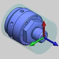
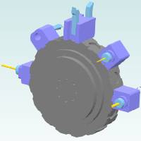
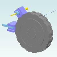
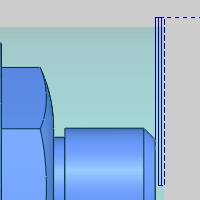
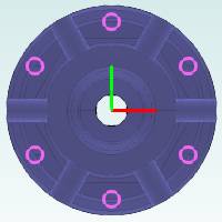
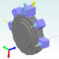
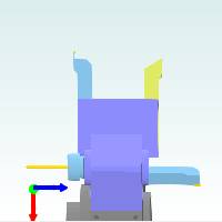
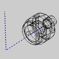
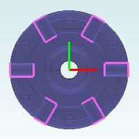
Machine Setups
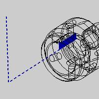
For this tutorial, all features are created using one of two machinesetups: one for the front side and one for the back side of the part. The following images show the location and orientation of the machiningorigin (work offset) for each setup.
|
Machine Setup1 |
Machine Setup2 |
|
|
The Mill Turn job, stock, and machine setups are already defined in the example file provided for this tutorial. If you would like to learn more, view the Mill Turn JobSetup Example.
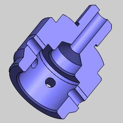
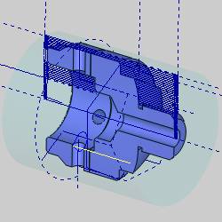
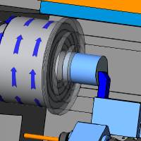
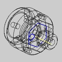
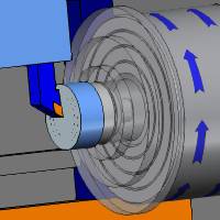
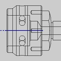
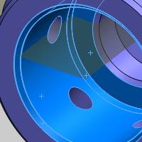
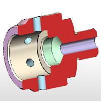
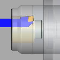
Final Result - All Toolpath
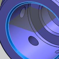
Next is a sectional view of the model that is used to show all of the toolpath created to machine the part in this tutorial.
Example File Download
If you are connected to the Internet, the part file for this example can be downloaded automatically by clicking the following link: Mill Turn Example 1.sldprt
Once you download and saved the zip file, extract the files on your system in an easy place to remember.You can then open the file to use with this tutorial. All files for the tutorials in this help system available for download can be found by clicking on the following link: http://www.bobcad.com/helpfiles.
In the example file provided, the job, stock, and two machine setups are already defined.
This tutorial highlights the following features of the BobCAM software:
- Loading the Tool Crib from a file
- Verifying Jaw Orientation
- Changing the default submachine for new features
- Creating Lathe features:
- Facing
- (OD) Turning
- Hole Drilling
- (OD) Grooving
- (ID) Turning or Boring
- Creating Mill features:
- Face milling
- Face drilling
- Cross drilling
- Using the various Posting modes for Mill Turn
- Geometry selection tips and using CAD features
- Using Modify Start Point for profiling
- Modifying machining strategies
- Changing tool assignment in the Tool Crib
- Simulating the program
- Verifying the tool assignment/tool numbering
- Posting the NC program (G-code)
Part 1) Load the Tool Crib from a Saved File
For this example, we load the Tool Crib with all tools that we want to use for the job. This way, we only open the Tool Crib to confirm the proper tool selection or to change the default assignment, for example, when selecting a finish tool for a rough operation.
Tip: The ability to save and load the Tool Crib is an invaluable tool that can save a significant amount of time when creating Mill Turn jobs in BobCAM. If you have resident tools and/or adapters, or tools and adapters that are generally always mounted to the turret of the physical machine, then you can load and mount these tools in the Tool Crib once, and then save the information to a file to use as a template. This way you can just load the file, and you only need to add additional tools as needed per job. You can even save a Tool Crib for each machine or each common configuration that you use.
- In the CAM Tree Manager, right-click Mill Turn Tools, and click Tool Crib.
The Mill Turn Tool Crib displays. - Click the Loadbutton.
The Open dialog box displays for you to select a previously saved toolcrib file. - Navigate to the MillTurn Example 1 folder, and click to select the MillTurn Example 1.mttcribs file, and clickOpen.
Notice that the upper turret and lower turret devices now contain all the adapters and tools needed to complete the entire job. The mounting parameters are already set as needed to match how we are mounting our tools on the physical machine. - Click OKto save the tool information to the job.
Part 2) Verify Jaw Orientation
- In the CAM Tree, right-click Mill Turn Job, and select Current Settings.
The Current Settings dialog opens on the default Machine Parameters page. - In the Chuck group, with MC (Main Chuck) highlighted, choose the appropriate Jaw Orientation and Clamp Direction.
- In the Chuck group, highlight SC (Sub Chuck) and choose the appropriate Jaw Orientation and Clamp Direction.
- Click OK.
The Current Settings dialog closes.
Note: In the case of this example part, leaving these at default is fine.
Part 3) Change the Default Submachine
The first three features that we create use the LT_MS (lower turret,main spindle) submachine or work zone. Instead of changing the submachine in the Posting page of each feature, we change the submachine in the Cam Tree to determine the default submachine for creating new features.
- Under MachineSetup - 1, right-click the current submachine name (UT_MS), and click Edit.
- Under SubmachineName, click the down arrow, and select LT_MS.
- Click OKto update the default submachine.
All machining features created under MachineSetup - 1 are automatically set to use this submachine. The submachine can always be changed in the Posting page of the wizard.
Part 4) Create a Turning Feature - Lathe End Face
Machine Setup 1
It is important to think about the machine setup (machining origin)when creating machining features for Mill Turn jobs. All of the features that we create to machine the front half of the part are created under Machine Setup 1. The machining origin for this machine setup is at the front face of the part, not the stock, (we are facing to zero).
To learn how to define the machine setups for this example file, view the Mill Turn Job Setup Example.
Add the Feature and Select Geometry
- Right-click MachineSetup - 1, point to Turn Features,and click Lathe End Face.
The Geometry Selection page appears.
Tip: The Lathe End Face feature is designed to face the part to zero. Because the front of our part is flush with the machine zero, and since the stock we are cutting extends beyond that, geometry selection is not necessary. Positioning your future parts with this in mind can save you a considerable amount of time!
- Click Next>>to go to the Feature settings.
Define the Feature, Machining Strategy, and Posting Settings
-
The Feature page of the wizard displays the stock settings that were automatically detected and set based on our stock geometry and work offset (machining origin) location from the Stock Wizard and Machine Setup. The software uses these values to determine the location of the first cut, and because they are automatically set, we do not need to modify these values for this feature.
In the Undercut group, select the Remove Primary Undercut option.
This will force it to ignore the groove geometry to allow us to handle that with a separate feature. -
Click Next>>to go to the Machining Strategy.
The default template, Rough, doesn't need changed, and we do not need a finish operation. We simply use the roughing operation to cut the face to its final depth. -
Click Next>>to go to the Posting settings.
-
Under PostingParameters, click the down arrow and select CannedCycles.
Note: Notice the Submachine group in the Posting page of the wizard. You can always change the submachine for the feature from this location, in the event it is different than the default submachine selected in the CAM Tree.
-
Click Next>> to go to the Tool settings.
Define the Rough Operation Parameters
Note: In this example, we loaded the Tool Crib before creating our job. This was done to show how much faster this method is, but you do not have to work this way. You can always load and mount tools in the Tool Crib as you create machining features. BobCAM allows you to work to your preferences.
Next we open the Tool Crib simply to verify the correct tool assignment(this step is not actually required, but is done for example purposes). We can determine which tool is selected by viewing the Tool Label, but it can also be helpful to open the Tool Crib to view and confirm the mounting orientation of the tool for each operation.
-
Click the ToolCrib button.
The Mill Turn Tool Crib displays.
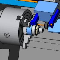
Notice in the device tree on the left that the 80 Deg.1/64 Rough Turningtool is selected under the lower turret Station #17 (the first station of the lower turret).
Note that only the lower turret displays in the device tree, because our feature is set to the LT_MS (lower turret,main spindle) submachine.
We can also see that the tool is properly mounted and oriented to face the front side of the part.
-
With the 80 Deg.1/64 RoughTurning tool still selected, click OK.
Important: When opening the Tool Crib from within a CAM Wizard, the tool that is selected when you click OK is assigned to the operation. Always be sure that the correct tool is selected before clicking OK in the Tool Crib.(The tool can be selected in the Device Tree or the Tool list.)
-
Click Next>> twice to go to the Parameters.
-
Under Parameters, makethe following changes:
-
Depth of Cut = 0.030
-
In the Finish Allowance group, set:
- Z Allowance= 0.00
-
X Allowance= 0.00
Notice that we set the allowance values to zero so that no extra stock remains after the rough operation (we are not using a finish operation).
-
At the bottom of the wizard, click Computeto calculate the toolpath.
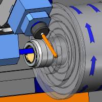
Simulate the Feature
Before creating another feature, we simulate to confirm the toolpath is correct. The following steps provide an example of some settings that you may want to use during simulation. You can use some or all of these settings when simulating other features later in this tutorial.
-
To open simulation, click
 above the CAM Tree, or right-click Mill Turn Job and select Simulation.
 -
The following provides some suggested simulation settings to get started.
- In the Simulation group of the Simulation tab, ensure
 Machine Focus is set.
 - On the Simulation tab,under Visibility, click down arrow under the
 MachineHousing button and ensure it is set to Show
. - Under Visibility, click the
 Toolpathbutton to hide the toolpath from view.
 - Confirm that the
 Workpiece and
  Stockbuttons are set to show the workpiece and stock.
 - Use the
 SimulationRunSpeed slider to adjust the playback speed of simulation as needed while simulating.
-
Click the
 Runbutton to play the simulation.
The simulation confirms that the desired toolpath is achieved.
-
To close the simulation, click the
 Exit Simulation button in the BobCAMmenu.
For more help with our extremely powerful simulation, view Getting Started with Simulation.
Hide Geometry and Toolpath
Now that our feature is finished, we can hide the toolpath from view and collapse the feature with the following steps.
-
In the CAM Tree, right-click FeatureLathe End Face, and click Blank/UnblankToolpath.
-
Click the arrow sign next to the feature to collapse it.
-
In the Filemenu, click Save.
Always be sure to save your work, and save it often.
Part 5) Create a Turning Feature - OD Turning
Now we create a turning feature to rough and finish the outside diameter(OD) of the part. Note that we are splitting the front and back half of the part, so the front half is machined on the main spindle and the back half is machined on the sub spindle.(This is why the model is split into two halves.)
Add the Feature and Select Geometry
-
Right-click MachineSetup - 1, point to Turn Features,and click Lathe Turning.
-
Click the SelectGeometry button to hide the wizard and show the graphics area.
-
Under Selection Options, click the Select Whole Bodies check box, and click the front half of the model in the graphics area.
-
To confirm the selection, click
 .
. -
Click Next>> to go to the Patterns page.
-
In the Undercut group, select the Remove Primary Undercut option.
This will force it to ignore the groove geometry to allow us to handle that with a separate feature. - Click Next>>to go to the Machining Strategy.
Define the Machining Strategy and Posting Settings
-
Under Template, click Rough / Finish.
The Current Operations list now displays one Turn Rough operation and one Turn Basic Finish operation. -
Click Next>>to go to the Posting settings.
-
Under PostingParameters, click the down arrow and select CannedCycles.
-
Click Next>>to go to the Tool settings.
Define the Rough Operation Parameters
-
We don't need to open the Tool Crib this time, as the software already assigned the appropriate tool (80 Deg.1/64 Rough).
-
Click Next>>to go to the Patterns.
- Set the System Compensation to On with Collision Detection, and select the Use Tool Holder option.
- Click Apply to All Operations.
-
Click Next>>to go to the Parameters.
-
Under Parameters,make the following changes:
-
Set the Depth of Cut to 0.040
-
In the Finish Allowance group, set Zto 0.0030
-
Click Next>> to go to the Rapids settings.
In the exit group, click the down arrow and selectRapid On Exit To Cycle Start X-Z.
This setting reduces the amount of tool movement between operations, as it returns to the cycle start instead of the homeposition defined for the tool. Note that this option moves in X first and then in Z as shown in the wizard image.
-
Click Next>> to go to the Leads settings and make the following changes:
-
Set the Lead-in to Custom, and set Lead-in Z to 0.100
-
Set the Lead-out to Custom, and set Lead-out X to 0.100
-
On the lower-left, click Applyto All Operations so that the finish operation uses the same leads settings.
Define the Finish Operation Parameters
In this part of the example, we show an important tip for tool assignment in Mill Tun jobs. We are using the same turning tool to rough and finish the part as this reduces the number of tools that we need to mount on the machine. Next, we change the tool assignment for the finish operation to use the rough tool.
-
In the tree on the left, under Basic Finish, click
 Finish.
 -
Click the ToolCrib button.
Note: At the bottom of the device tree, notice there is a tool under the Loose tools category. This is the tool that the system automatically assigned because our tool crib (lower turret) does not contain any lathe finish tools. Next, we change this operation to use a tool from the rough category.
-
On the lower-left under ToolCategory, click Lathe Rough.
Tip: You can select a category under Tool Category to filter the tools list to show only tools from that category, which makes it easier to locate the appropriate tool. This is extremely helpful when there are a lot of tools in the job.
-
Click to select the only tool in the tools list, 80Deg.1/64 Rough Turning.
Notice that the tool also highlights in the device tree to show its location.
Click OK.
-
You can go to the Leads settings and confirm that they are already set from using Apply to All Operations earlier (this step is optional).
-
At the bottom of the wizard, click Computeto calculate the toolpath.
Simulate the Feature
Next we simulate the program to view the second feature operations.
-
In the BobCAMmenu, click
Simulation. -
In the information and analysis tabs on the right, click the Move Listtab to show it.
-
At the top of the list, click Op.2: Turn Rough-80 Deg 1/64 Rough Turning to advance the simulation to the start of the rough turning operation.
Tip: In the Move List tab of the simulation window, you can click the operations in the list to go directly to the start of the selected operation.
-
Click the
Runbutton to play the simulation.
Again, we are happy with the result, so no changes are needed for this feature.
-
To close the simulation, click the
Exit Simulation button.
Hide Geometry and Toolpath
As shown earlier, we can hide the toolpath with the following steps.
-
In the CAM Tree, right-click the second FeatureLathe Turning, and clickBlank/UnblankToolpath.
-
You can also click the small arrow next to the feature to collapse it.
-
In the Filemenu, click Save.
Part 6) Create a Lathe Hole Feature
Next we drill the hole in the front of the part using a lathe drilling operation, because this hole is centered on the front face of the part.
Add the Feature and Select Geometry
-
Right-click MachineSetup - 1, point to Turn Features,and click LatheHole.
-
Click SelectGeometry, and click the cylindrical surface of the hole on the front face of the model.
-
Click
 to confirm the selection.
 -
Click Next>>to go to the Feature settings.
Define the Feature, Machining Strategy, and Posting Settings
-
Notice that the Diameter,Top of Feature, TotalDepth, and Through Holestatus are automatically set based on our selection.
-
Click Next>>to go to the Machining Strategy.
-
Under Template,click Hole.
- Under Current Operations, withLathe Center Drill selected, and click
 (Delete Operation).
The Current Operations list now contains one Lathe Drill operation. -
Click Next>>to go to the Posting settings.
-
Under PostingParameters, click the down arrow and select CannedCycles.
-
Click Next>>to go to the Tool settings.
Define the Operation Parameters
-
Click ToolCrib and confirm that the 1/2Drill tool is selected under Station #19 (the third station of the lower turret).
-
Click OKto close the Tool Crib, and click Next>>to go to the Parameters.
-
Under CycleType, click Peck.
-
No other changes are needed for this operation. Click Compute to create the toolpath.
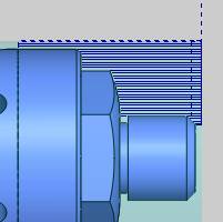
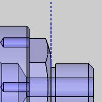
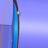
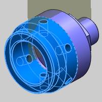
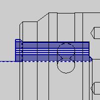
The following images use the Wireframe view.(In the View menu, point to Display and select Wireframe.)
Tip: Turningon the Wireframe view is a great way to confirm the proper toolpath is created, especially for turning features, whether internal or external. When the shaded view is used, there may be toolpath inside the model that is obscured by the geometry.
Simulate the Feature
-
Simulate the feature using the steps explained earlier to confirm the desired result.
-
Close the simulation.
-
You can now hide the toolpath and collapse the feature as explained earlier.
Part 7) Change the Default Submachine
The next three features that we create use the UT_MS (upper turret,main spindle) submachine, so we want to change the default submachine again. Changing the submachine this time is slightly different than the first time as features already exist, so we are prompted to confirm which features we want to change.
-
Under MachineSetup - 1, right-click the current submachine name (LT_MS), and click Edit.
-
Under SubmachineName, click the down arrow, and select UT_MS.
-
Click OKto update the default submachine.
-
A message displays to ask whether or not we want to change the submachine in existing features. We only want to change the default submachine for new features, so we click No.
All new machining features we create under Machine Setup - 1 now use the new submachine. The submachine can always be changed in the Posting page of the wizard.
Part 8) Create a Turning Feature - OD Grooving
Our next feature cuts a groove on the OD of the antithesis is the last operation that we perform using the main spindle, before creating our part transfer to the sub spindle. We create our grooving operation first and then edit the feature to add our part transfer using MDI (manual data input).
Add the Feature and Select Geometry
-
Right-click MachineSetup - 1, point to Turn Features,and click Lathe Groove.
-
Click SelectGeometry.
-
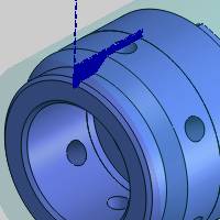
Click to select the three faces that makethe groove on the front of the part as shown next.(Be sure to select the faces and not surface edges.)
You need to rotate the model and zoom-into select the last face of the groove.
-
Click
. -
Click Next>> twice to go to the Machining Strategy.
Define the Machining Strategy and Posting Settings
-
Under Template,leave Groove Rough selected.
Notice in the Current Operations group, we only have a Groove Rough operation. -
Click Next>>to go to the Posting settings.
-
Change the PostingParameters to Canned Cycles.
-
Click Next>>to go to the Tool settings.
Define the Operation Parameters
-
Again, we can see the appropriate tool (1/8OD Groove) is already assigned. You can open the Tool Crib to confirm the appropriate settings for the tool if desired.
-
Click Next>>to go to the Patterns.
- In the Pattern group, select Single Pass.
Since the tool is the same width as the groove we are trying to accomplish, a single pass is all we need. - Click Next>>to go to the Parameters.
-
Under Parameters,set the X value of the Finish Allowance to 0.000.
Because we are using a single operation to cut the groove, we remove the allowances.
The leads will be left as they are.
-
Click Compute.
-
Simulate the feature, hide the toolpath, and collapse the feature.
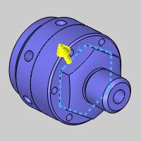
Part 9) Create a Mill 2 Axis Feature - Face/Z-axis Milling
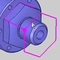
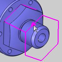
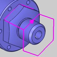
The next feature that we create cuts the hexon the front of the part using a single operation to remove the materialthat remains after our turning operation. Again, we alter the tool assignment so that we can use a finish tool with a rough operation type.(This is done for illustrative purposes, as otherwise you could use a profile finish operation to accomplish the same task.)
Add the Feature and Select Geometry
-
Right-click MachineSetup - 1, point to Mill Features,and click Mill 2 Axis.
-
Click SelectGeometry.
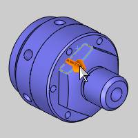
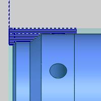
For this feature, we could assign a CAD feature, but instead we use one of the loop selection methods from SolidWorks.Point to the surface edge at the bottom of the hex so that it highlights.
Right-click the edge (while it is highlighted)and click Select Loop.
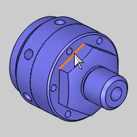
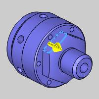
When the yellow loop selector arrow displays, click it to change the selected loop to go around the hex.
-
Click
to confirm the selection. -
Click Next>> to go to the Feature settings.
Define the Feature, Machining Strategy, and Posting Settings
-
Notice that our Top of Feature (0.00) and Total Depth (1.7050) are automatically set from our selections.
-
Click Next>>to go to the Machining Strategy.
The default template, Profiling, doesn't need changed, but we remove our finish operation. -
Under CurrentOperations, click to select ProfileFinish, and click
(Delete Operation). -
Click Next>>twice to go to the Posting settings.(We are not using Tabs.)
-
Under PostingMode, click Polar Interpolation.
Tip: PolarInterpolation is a mode in which the code is posted using XYZ coordinates that are then converted by the machinecontroller to XZC coordinates. This setting can be used to create more accurate machining and superior surface finishes compared to longhandcode, but the machine controller mustsupport Polar Interpolation and be configured to use it.
-
Click Next>>twice to go to the Tool settings.(We do not change the MultiaxisPosting settings).
Define the Profile Rough Operation Parameters
The following tool assignment is another example of changing tool categories to select a tool that is not the same as the operation type (finish tool for a rough operation type). The software already assigned an appropriate tool for the operation, but it selected a tool from the rough category and added it to the Loose tools. The tool that was already loaded in the Tool Crib is a finish tool, and we want to select this tool as we have already mounted it.
-
Click ToolCrib.
-
Under ToolCategory, click Endmill Finishto filter the tools list.
-
Click to select the only tool in the tools list, 1/2 Flat Endmill - Long,and click OK.
-
On the left under ProfileRough, click Parameters.
-
Change the SideAllowance value to 0.000,because we are only using a single operation.
-
Click Next>>to go to the Leads settings.
Under Lead-in, click Blend.(Notice that our lead-out is also set to use the same settings.) -
Click Compute.
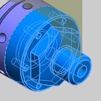
Notice that no toolpath is visible. This is due to our default chain direction and our compensation setting of left, which caused the toolpath to compute inside of the profile.
To view the current toolpath, in the View menu, point to Display,and click Wireframe.
(To return to the previous view, in the View menu, point to Display,and click Shaded with Edges.)
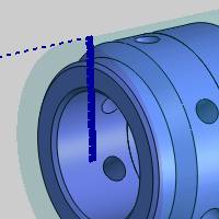
Modify the Start Point
Now we use Modify Start Point to change our chain direction and the starting location of the toolpath.
-
In the CAM Tree under Feature2 Axis, right-click DefaultChain Start Point and click Modify.
The feature preview displays with the start point indicator.
-
Click near the middle of the line as shown next.
The start point changes to the nearest snap point (in the middle of the line).
-
Now to reverse the direction, click the start point indicator directly.
This time the direction reverses.
-
Now we must confirm our selection, but be sure to not click anywhere else in the graphics area as the start point updates to the nearest snap location. Click
. -
To update the toolpath, right-click ProfileRough, and click Compute Toolpath.(You can also right-click the feature name.)
Simulate the Feature
It is suggested that you simulate the program after each feature you create. This makes it much easier to find mistakes and resolve them immediately.
-
On the BobCAM Command Manager tab, click the
 Simulationbutton.
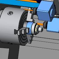
Confirm that no changes are needed by running the simulation. Note again that you can use the Move List to go directly to the operation you are verifying.
You can also use the Report tab to checkfor any reported collisions during the simulation. Note then when using the manual navigation, as explained earlier, the report tab displays a message to tell you that collision checking was not performed for the operations that were skipped.
-
Close the simulation.
-
Hide the toolpath and collapse the feature.
Part 10) Create a Mill Drill Hole Feature - Face/Z-axis Drilling
Next we create a Mill Drill Hole feature to drill the circular holepattern on the face of the model. For Mill Turn jobs, this is called face standard drilling (the tool is parallel to the Z-axis).
Add the Feature and Select Geometry
-
Right-click MachineSetup - 1, point to Mill Features,and click Mill Drill Hole.
-
Click SelectGeometry.
Notice in the Hole Selection Manager that the default drilling type is Standard Drill, which is used for drilling along the Z-axis. Be sure to select the appropriate drilling type before confirming your geometry selections. -
Expand the Feature Manager design tree and select the following CAD features: 1/4(0.25) Diameter Hole1 and CirPattern1.
-
Click
to confirm the selection.
Tip: Selecting cylindrical surfaces (or CAD features) allows the software to automatically detect and set the Feature parameters in the wizard for you.
-
Notice that the diameter, depth, and through hole status are automatically set.
-
Click Next>> to update the wizard tree.
Define the Feature, Machining Strategy, and Posting Settings
In the Feature page, we can see that the software automatically set the Diameter, Top of Feature, and Total Depth because we selected a CAD feature (cylindrical surfaces). The software also automatically creates Hole Groups for all holes with these same feature parameters. This feature results in a single hole group.
-
Click the GroupRetracts button, you can see that the Clearance Plane Heightvalue is automatically set based on our geometry selection, clearance settings, and machining origin (work offset) position.
The Group Retracts determine the rapid movement to clearance between hole groups, not within them. For our rapid movement between holes, we use the Rapid Plane. For this model, we need to increase our rapid plane to clear the boss in the center of the model.
To position the turret out of the way for our transfer, set the Type to Cylinder, and the Radius value to 10.000.
(Click OK to close the dialog box.)
-
Change the Rapid Planevalue to 0.7500.
Under HoleGroups, click anywhere in the row of Group1 to select it and display the hole groups preview directly inside the wizard.
Tip: To modify the viewing orientation of the hole groups preview, click and drag to rotate the view (left or middle mouse button). To pan the view, hold Ctrl and drag with the middle mousebutton. Use the middle mouse button (roll forward or backward) to zoom in or out.
The Hole Groups preview is very helpful in confirming the proper selections and feature parameters. Again, more information is available in this help system.
-
Click Next>> to go to the Machining Strategy.
-
Under Template, clickHole.
Under Current Operations, click to select Center Drill, and click (Delete Operation). -
Click Next>> twice to go to the Posting settings.
Under Posting Mode, click Longhand Code.
This posting mode uses C-axis motion to drill the holes, as compared to the Auto/Y Axis Mode which uses Y-axis movement to drill the holes. If the submachine does not have Y-axis capability, Auto/Y Axis Mode and Longhand Code produce the same result. -
Click Next>> twice to go to the Tool settings.(We do not change the Multiaxis Postingsettings).
Define the Operation Parameters
-
Click ToolCrib and confirm the appropriate tool (1/4Drill) is automatically assigned.
Click OK. -
Click Next>>to go to the Parameters.
Notice the Hole Groups list. When changing the parameters for holegroups, it is important that you select a group in the list before changing any settings. For this example, we use the default parameters. -
Click Compute.
-
Simulate the feature, hide the toolpath, and collapse the feature.
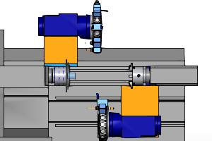
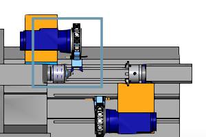
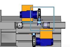
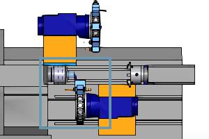
Part 11) Create a Part Transfer Using MDI (Manual Data Input)
For Mill Turn jobs, the MDI page of the wizard allows you to manuallydefine machine movements by combining commands to create lines of code. This is used to handle the movement of machine axes that do not have a specific operation, such as part transfers, cutoff/transfer, parts catchers,steady rests, and tailstocks. We define our part transfer after the grooving operation as it is the last operation we perform on the main spindle before transferring the part to the sub spindle. Be sure to have your chuck jaws oriented properly in your machine definition. For more information on the chuck configuration, see The Chuck Configuration topic.
Note: You can create your own generic MDI files (templates) that are customized for your machine to handle transferring the part from the main spindle to the sub spindle. The expected workflow is to define a process once using MDI, save it to a file, then simply load the saved file and change a few values as needed per job. We do the same for this example using the generic part transfer MDI file that is installed with the software. Contact Support for assistance with MDI features: [email protected] / (727) 489-0003
-
In the CAM Tree, right-click the last Feature Mill Hole-Blind - 0.2500 feature (that we just created), and click Edit.
The Lathe Wizard displays for you to make changes to the feature. -
In the tree on the left, click MDI.
-
Notice the Save/Loadgroup under the Task List. Click the
 (Load) button.
The Open dialog box should display with the correct location already selected: C:\BobCAD-CAM Data\**Current Version**\Features.If not, navigate to this folder. -
Click to select GenericPartTransfer.bcmdiand click Open.(Alternatively, you can double-click the file name to open it.)
The Load MDI Task dialog box displays. This dialog box allows you define exactly what tasks are overwritten with the information from the file. This allows you to load individual tasks from the saved file, but for this example, we use the full replace. -
Click OKto replace the entire current Task List with the information storedin the file.
You can see that only the After Operation task contains any commands(it has the plus sign icon). Click the plus sign to expand the After Operation folder and view all the lines that are already defined. All of our commands are under the After Operation task, because our part transfer happens after the grooving operation. -
We don't need to make any changes to our generic MDI parameters, but a few of the important commands that you may adjust per job are listed next.
Important Command Values:
|
Command |
Value |
|
Orient Main Spindle |
Angle |
|
Orient Sub Spindle |
Angle |
|
Move Sub Spindle to Clearance |
Axis |
|
Start Fast Feed Up to Part |
Axis and Feedrate |
|
Feed to Pickup Location |
Axis and Feedrate |
|
Part Transfer |
Part Pickup Position |
|
Send Sub Spindle Home |
Work Offset and Axis |
Note that the number of parameters that you need to adjust depends on the way you work. Many of these values may never be changed from the values defined in the MDI template file.
Tip: You modify commands on the MDI page using the Parameters group. The general process is as follows:
• Expand a ![]() Task to view the Lines under it.
Task to view the Lines under it.
• Expand a ![]() Line to view the Commands under it.
Line to view the Commands under it.
• Click to select a ![]() Command.
Command.
• All available parameters display under Parameters at the bottom of the MDI page.
• Update the values as needed.(The changes you make are reflected in the Task List.)
-
Click Finish to update the feature with the MDI part transfer.
Our part transfer is now output in the code, and is also visible in simulation (without MDI, in simulation the part just switches spindles without showing the transfer movement). -
Simulate the program to view the part transfer.
Part 12) Change the Default Submachine for Machine Setup 2
Now that the part is transferred to the sub spindle, all of our machiningfeatures for the second half of the part are created under Machine Setup2, which is set to Work Offset 2.Most of the remaining features use theUT_SS (upper turret, sub spindle) submachine, so we set the default submachine for creating features under Machine Setup 2.
-
Expand MachineSetup - 2 (if needed), right-click the current submachine nameUT_MS, and click Edit.
-
Change the Submachineto UT_SS (upper turret, subspindle), and click OK.
-
You can also collapse Machine Setup 1 to minimize the CAM Tree and reduce the need for scrolling.
Part 13) Create a Turning Feature - Lathe End Face
Now we begin to machine the back half of the part by creating another facing cycle to cut the stock to zero.
Machine Setup 2
Next we begin to create features under Machine Setup 2 to machine the back half of the part. If you would like to learn how to define this machinesetup, view the Mill Turn JobSetup Example.
Add the Feature and Select Geometry
-
Right-click MachineSetup - 2, point to Turn Features,and click Lathe End Face.
-
Click Next>>twice to go to the Machining Strategy.
Define the Feature, Machining Strategy, and Posting Settings
-
The Feature page of the wizard displays the stock settings that were automatically detected and set based on our stock geometry and work offset (machining origin) location from the Stock Wizard and Machine Setup. The software uses these values to determine the location of the first cut, and because they are automatically set, we do not need to modify these values for this feature.
-
Click Next>>to go to the Machining Strategy.
The default template, Rough, doesn't need changed, and we do not need a finish operation. We simply use the roughing operation to cut the face to its final depth. -
Click Next>>to go to the Posting settings.
-
Under PostingParameters, click the down arrow and select CannedCycles.
- Click Next>> to go to the Tool page.
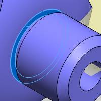
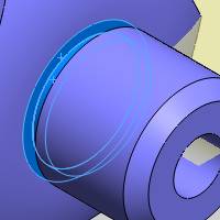
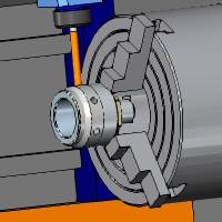
Define the Face Rough Operation Parameters
-
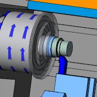
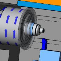
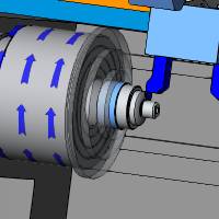
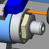
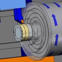
Confirm that the 55Deg.1/32 Rough Turning tool is selected under Tool Data.(As always, you can open the Tool Crib to confirm the proper tool selection and mounting).
-
The following image shows the tool we select(it is highlighted with the yellow holder). You can see that the tool is mounted with the correct orientation for machining the back side of the part (on the sub spindle).
-
Click Next>>twice to go to the Parameters.
-
Under Parameters,make the following changes:
-
Set the Depth of Cut to 0.0350
- Set the Z, and X values in the Finish Allowance group to 0.000.
-
Click Compute.
-
Simulate the feature and confirm that no changes are needed.
-
Hide the toolpath and collapse the feature.
Part 14) Create a Turning Feature - OD Turning
The next feature is created to rough and finish the remaining stock material on the back half of the part. In this part, we use the SelectWhole Bodies option and learn how to modify the section planes to getthe desired profile from the model.
Add the Feature and Select Geometry
-
Right-click MachineSetup - 2, point to Turn Features,and click Lathe Turning.
-
Click SelectGeometry.
-
Click the SelectWhole Bodies check box, and select the back half of the model.
You can see that the first section plane preview is in the center of the through hole in the model. For this reason, we change our section plane start angle to avoid the through hole. -
Under LatheParameters, change the StartAngle to 30.00 degrees.
The same result can also be achieved by selecting the Spun Profile option. -
To confirm the selection, click
. -
Click Next>>twice to go to the Machining Strategy.
Define the Machining Strategy and Posting Settings
-
Under Template, select Rough / Finish selected.
The Current Operations list now displays one Turn Rough operation and one Turn Basic Finish operation. -
Click Next>>to go to the Posting settings.
-
Under PostingParameters, click the down arrow and select CannedCycles.
-
Click Next>>to go to the Tool settings.
Define the Rough Operation Parameters
-
Confirm that the 55Deg.1/32 Rough tool is selected under Tool Data.
-
Click Next>>.
- In the Compensation group, set the System Compensation to On with Collision Detection, and select Use Tool Holder.
- Click the Apply to All Operations button.
-
Click Next>>.
-
Under Parameters,make the following changes:
-
Set the Depth of Cut to 0.0350
-
In the Finish Allowance group, set the Z value to 0.0030
-
Click Next>> twice to go to the Leads settings and make the following changes.
-
Set the Lead-in to Custom, and set Lead-in Z to 0.100
-
Set the Lead-out to Custom, and set Lead-out Z to -0.0500
Note: Notice that we used a negative lead-out, which creates an overlap in the toolpath where the front turning operation and back turning operation meet.(The toolpath extends past the selected geometry.)
-
Click Apply to All Operations.
Define the Finish Operation Parameters
-
Under Turn Basic Finish, click Finish.
-
Click ToolCrib.
-
Under ToolCategory, click Lathe Rough.
-
Click to select the 55Deg.1/32 Rough Turning tool in the tool list, and click OK.
-
Click Compute.
-
Simulate the program and confirm the desired result.
-
Hide the toolpath, collapse the feature, and save the file.
Part 15) Create a Lathe Hole Feature
The next feature drills a large hole in the back of the part to prepare it for the boring operation we create afterward. Our drill for this operation is on the lower turret, so this feature provides an example of changing the submachine for the feature using the Posting page.(This is the only feature under Machine Setup 2 that doesn't use the UT_SS submachine.)
Add the Feature and Select Geometry
-
Right-click MachineSetup - 2, point to Turn Features,and click Lathe Hole.
-
Click SelectGeometry.
-
Click the cylindrical surface inside of the model.
-
Click
. -
Click Next>>.
Define the Feature Machining Strategy and Posting Settings
-
Notice that Feature Parameters are all automatically set based on our selection.(Diameter = 1.250, Top of Feature = 0.00, and Total Depth = 2.000.
Click Next>>. -
Under Template, click Hole.
-
Delete the Lathe Center Drill operation from the Current Operations list.
-
Click Next>>.
-
Under PostingParameters, click the down arrow and select CannedCycles.
-
Change the Submachineto LT_SS (lower turret, subspindle).
-
Click Next>>to go to the Tool settings.
Define the Operation Parameters
-
Click ToolCrib.
Notice there is a 1.250 diameter drill under the Loose tools item at the bottom of the device tree. The software automatically assigned this tool for the feature, but we want to change it to a tool we already mounted in the Tool Crib. -
Click to select the 1.250Dia.118 Deg.tool under Station19, and click OK.
-
Click Next>>.
-
Under CycleType, click Peck.
-
Click Compute.
Hide the toolpath and collapse the feature. You can also turn on the Shaded with Edges view if you changed it earlier.
-
Simulate the feature.
Part 16) Create a Turning Feature - Boring
Next we create a boring feature to finish clearing the material on the inside (ID) of the part.
Important: When creating Turning features for boring, it is important that you select a boring tool (a tool from the boring category) in order to create proper simulation of the operation.(The boring tool type is handled differently in simulation.)
Add the Feature and Select Geometry
-
Right-click MachineSetup - 2, point to Turn Features,and click Lathe Turning.
-
Click SelectGeometry.
For this feature, the geometry we need to select is contained on both bodies, and we don't want to create toolpath in the area that was cleared by the previous drill operation. This time, we simply select the surfaces directly from the model for the area we want to create toolpath. Selecting geometry this way can be very helpful for turning features, and (as in this scenario) may be the most efficient method. -
Click to select the five faces of the model as shown next. The selections span from the chamfer at the back of the part up to the chamfer that meets with the drill hole geometry.

-
Click
. -
Click Next>>.
Define the Feature, Machining Strategy, and Posting Settings
-
Under Feature Parameters, change the Feature Type to ID.
-
Click Next>>.
-
Set the Template toRough / Finish , and click Next>> twice.
Define the Rough Operation Parameters
-
Click ToolCrib.
-
Under ToolCategory, click Lathe Boringto filter the tools list.
-
Select the only tool in the tools list, 80 DEG 1/64 CRAD 3/4 INCH BORING BAR.
-
Click OKto assign the tool to the operation.
Click Next>>. - In the Compensation group, set the System Compensation to On with Collision Detection, and select Use Tool Holder.Click Next>>.
-
Update the Parameters as follows:
-
Set the Depth of Cut to 0.0400
-
Set the Z value in the Finish Allowance group to 0.0030
- Leave the X value alone
- In the Bounds group select the Trim To Stock option. This will force the toolpath to avoid the portion of stock already removed by our previous operations.
-
Click Next>>twice, and update the Leads settings as follows:
-
Set the Lead-in to Custom, and set Lead-in Z to 0.100
-
Set the Lead-out to Custom, and set Lead-out X to 0.0500
-
Set the Lead-out to Custom, and set Lead-out X to 0.0500
-
ClickApply to All Operations
Define the Finish Operation Parameters
-
Under TurnBasic Finish, click Finishto go to the Tool settings.
-
Click ToolCrib.
-
Under ToolCategory, click Lathe Boring.
-
Select 80DEG 1/64 CRAD 3/4 INCH BORING BAR and clickOK.
You can check the Leads settings of the finish operation to confirm that they are the same as the rough. -
Click Compute.
-
Hide the toolpath, collapse the feature, and simulate the feature.
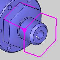
Part 17) Create a Mill Hole Feature - Cross Drilling
For the final operation, we create a drilling feature to handle the cross drilled holes in the model. Cross (or radial) drilling means that the tool axis crosses the center line of the part (the tool is parallel to the X-axis). What is important here is selecting the drilling type, Cross Drill, in the Hole Selection Manager.
Add the Feature and Select Geometry
-
Right-click MachineSetup - 2, point to Mill Features,and click Mill Drill Hole.
-
Click SelectGeometry.
-
In the Hole Selection Manager, next to Standard Drill, click the down arrow and select Cross Drill.
Important: When selecting geometry for Mill Drill Hole features, it is important to select the proper drilling type based on the orientation of the holes, as the software filters your selections accordingly.(Standard Drilling is parallel to Z-axis, Cross Drilling is perpendicular to [and intersects or crosses]the selected Rotation Axis, and Multiaxis Drilling is any orientation.)
-
Click the Select Whole Bodiescheck box, and click to select the back half of the model.
-
Click
. -
Click Next>> to go to the Feature settings.
Define the Feature, Machining Strategy, and Posting Settings
-
Under MaterialApproach, click Group Retracts.
Notice that our clearance Type is automatically set to Cylinder and the Radius value is 2.2500.The software automatically selects a cylindrical clearance for cross drilling and sets the Radius value based on the stock and clearance settings from the Stock Wizard and Machine Setup.(Note that the Group Retracts handle the clearance movement between hole groups and not within them. The Rapid Plane determines the rapid clearance movement within hole groups.) -
Click OK.
-
Under HoleGroups, click anywhere in the row of Group1 to select it and display the hole groups preview inside of the wizard.
Using the Hole Groups preview is a great way to confirm the proper feature settings before computing the toolpath.
Notice the Diameter, Top of Feature, and Feature Depth values are all automatically set.
-
Click Next>>.
-
Select the Hole template, and delete the Center Drilloperation from the Current Operationslist.
Click Next>> to update the wizard tree with the new template. -
Under Drill, click Drill to go to the Tool settings.
You can open the Tool Crib to confirm that the assigned tool is indeed mounted for cross drilling. It is important that you select a tool in the proper orientation for the operation you are creating.
Confirm that the 3/8Drill tool is selected and click OK.
-
Click Compute.
Part 18) Final Simulation
Now that all of our features are created to machine the entire part, we can simulate the program to confirm the desired result for the entire job.
Important: For Mill Turn Jobs, you cannot post or simulate the program unless all tools are mounted in the Tool Crib. For example, when the software cannot find the appropriate tool in the Tool Crib during tool assignment, it assigns a tool from the Tool Library and places it under the Loose tools item in the device tree. Loose tools are tools that are assigned to an operation, but not mounted. All Loose tools must be mounted before simulating or posting. You can open the Tool Crib to confirm there are no unmounted(Loose) tools before simulating or posting the program.
-
In the CAM Tree, right-click MillTurn Tools, and click ToolCrib.
Note that when you open the Tool Crib from the CAM Tree, all tool devices on the machine display in the device tree.
-
In the device tree on the left, drag the slider down to view the Loose tools and confirm there are none. Note that there is one Loose tools item per device, so be sure to check both (all) devices for Loose tools.
Important: BobCAMuses a special convention for Loose (unmounted) tools. The Tool Number for loose tools is -1 (negative one). When you see a tool with a tool number of -1, you know that you need to mount it (or assign a different tool to the corresponding operation).The easiest way to see where a loose tool is assigned is to open the Assigned Tools dialog box (right-click Mill Turn Tools, and click Verify Tool Assignment). This dialog box lists all features to which each tool is assigned.
-
For our example, there are no loose tools, so we are ready to simulate the program.
-
Right-click Mill Turn Job,and click Simulation.
For more help using simulation, view GettingStarted with Simulation.
Part 19) Verify Tool Assignment and Tool Numbering
Mill Turn jobs contain three different methods for defining the toolnumbering. The default method (Use Station #) automatically numbers the tools based on the station to which they are mounted. This is commonly used on machines that contain one or more turrets and is also adapted to work well for 5-axis applications in which the machine is equipped with a milling head. The second method (Use Tool ID) utilizes the ToolID to guarantee a unique number is assigned to each tool. The final method(Manual) provides a completely user-defined or manual tool numbering schemein which the software loads the tool number stored in the Tool Library,which you can modify as needed.
The following steps show you how to confirm proper tool numbering after creating all features for the job.(Note that you can also define your tool numbering while you create the job, as the same options are available in the Tool Crib.)
-
In the CAM Tree, right-click MillTurn Tools, and click VerifyTool Assignment.
The Assigned Tools dialog box displays. This dialog box lists all tools that are actually used in the job (assigned to an operation) and lists various information about them.
-
Confirm the appropriate tool numbering for the job and makeany changes as needed.
Note: The tool offset numbers for each operation are set in the Tool page of the CAM wizards. The BobCAM software always sets the offset numbers to matchthe tool number unless you use Override Offsets to define the offset number manually.
-
After confirming all tool numbering, click OKto close the dialog box.
Part 20) Post the Program
After simulating the program and confirming our tool numbering, no changes are needed so we are ready to post the program and create the NC program(G-Code).
-
Right-click MillTurn Job, and click Post.(Alternatively, you can click Post and Save As if you would like to select a different location to which the file is saved. The default location is the BobCAM Data NC folder.)
The NC program displays in the BobCAM Posting Manager. -
You can view the code from this location you can also right-click anywhere in the window to access another shortcut menu, for example, for opening the code in the Editor.
-
Save the file.
Congratulations! You have completed the Mill Turn Example 1 tutorial. Much more information about Mill Turn jobs is available in this Help system.