


Mill Turn Job Setup Example
Introduction
This topic explains how to create the Mill Turn job, stock, and machinesetups for the Mill Turn Example 1 tutorial (but applies to any Mill Turnjob). These items are already defined in the example file provided for the tutorial, so this topic provides the complete steps for those who want to learn more about the job setup.
Overview
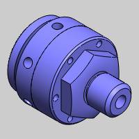
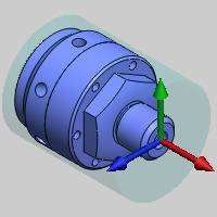
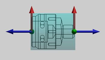
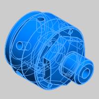
We have created our part model in the location and orientation that we want to use, so we are ready to create the job, stock, and two machinesetups.
Example File Download
If you are connected to the Internet, the part file for this example can be downloaded automatically by clicking the following link: Mill Turn JobSetup Example.sldprt
Once you download and saved the zip file, extract the files on your system in an easy place to remember.You can then open the file to use with this tutorial. All files for the tutorials in this help system available for download can be found by clicking on the following link: http://www.bobcad.com/helpfiles.
This tutorial highlights the following functionality of the BobCAM software:
-
Creating a Mill Turn job
-
Adding Machine Setups to the job
-
Defining Stock using the Stock Wizard
-
Defining the Machine Setup parameters
-
Setting the spindle per setup
-
Aligning the machining origin
-
Defining the Work Offset parameters
-
Automatic Mill Turn Clearance settings
-
Assigning workpiece geometry
Part 1) Create the Mill Turn Job
-
In the BobCAM CAM Tree, right-click
 CAM Defaults,and click New Job.
 -
Under JobType, click to select MillTurn.
-
Under Machine,click the down arrow, and select BC_2T_2S.
Note: Normally, we would click Stock Wizard now to go directly to defining the stock and machine setup. For this example, we are utilizing two machine setups (one for the front of the part and one for the back), so instead we create a second machine setup first. This allows us to define both machine setupsat the same time for the purposes of this tutorial. You may not want to create the second machine setup until you are finished creating machiningfeatures under the first machine setup. The information here applies to any workflow you prefer to use.
-
Clear the Start Stock Wizard check box.
- Click OK to create the Mill Turn job and add it to the CAM Tree Manager.
Part 2) Add the Second Machine Setup
-
In the CAMTree, right-click Mill TurnJob, and click Add Setup.
This adds another machine setup to the Cam Tree.(Machine Setup 2 is added below Machine Setup 1.)
(Alternatively, you can right-click any MachineSetup, point to Additional Functions, and click Insert Setup.)
We are now ready to create the stock and define both machine setups.
Part 3) Create Stock Geometry Using the Stock Wizard
For the first half of the example, we use the isometric view.(Press Ctrl+7).
-
Right-click Stock,and click Stock Wizard.
-
Under Stock Type, click to select
 (Cylindrical).
The software automatically detects the solidmodel in the graphics area and creates a bounding stock. We can see that the default extrusion direction (Z Axis) needs updated for our part orientation.
-
Under Stock Orientation,change the Extrusion Directionto X Axis.
-
Under Offset, change the
 (Diameter Offset) value to 0.250.(Press Tab to update the stock preview.)
-
Change the
 (Start Face Offset) value to 0.100.
Change the ![]() (End Face Offset)value to 0.100.
(End Face Offset)value to 0.100.
-
Click
 to go to the Machine Setup.
Part 4) Define Machine Setup 1
Select the Machine Setup and Spindle
-
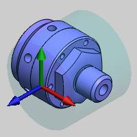
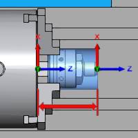
Notice at the top of the Machine Setup windowthat Machine Setup - 1 is selected. We use this machine setup for all features that are used to machine the front half of the part.
-
Confirm that the default, LeftSpindle, is selected as this machine setup is created for the main (left) spindle.
Set the Machining Origin
-
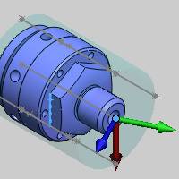
Next we define the machining origin for MachineSetup 1. You can see that the software automatically created bounding entities in the graphics area to assist with the origin selection.

Under Origin, the Pick Origin box is already selected so we can select the origin from geometry in the graphics area.
-
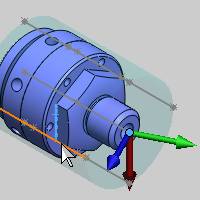
Click to select the point at the front of the stock.
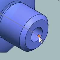
The origin updates to the selected point.
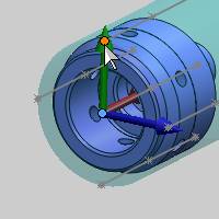
Modify the Direction of the Machining Origin Axes
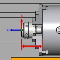
Next we modify the direction of the machiningorigin axes to align it to the machine zero (coordinate system). We need the Z-axis to be at the center line or rotation axis of the part to matchthe Z-axis of the machine.
-
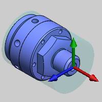
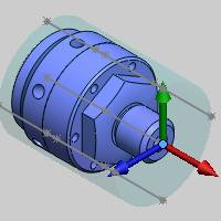
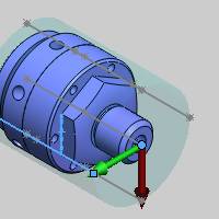
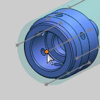
Under Origin,click in the X Axis box, and click to select the vertical edge of the model as shown next.
The X-axis direction of the machining origin updates (shown by the red arrow) based on our geometry selection.
-
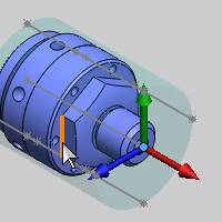
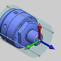
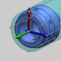
Click in the Z Axis box, and click to select the line on the side of the part.
The Z-axis direction of the machining origin is now parallel to the selected line, but is currently backwards, so next we use the reverse direction button.
-
Next to Z Axis, click the
 (reverse) button.
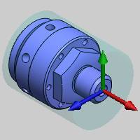
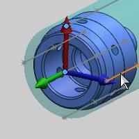
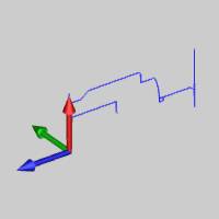
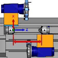
Note: For Mill Turn jobs, you have the freedom to create and orient the part anyway that you like, thus you must orient the machining origin as needed to accommodate your part orientation. An important note here is that the software analyzes the part model in the XZ plane when creating turning features.(The XZ plane is the default, which can be modified during geometry selection.) Also, if you want to use sketches for lathe profiles, create them in the XZ plane of the machining origin to reduce the need to change parameters during geometry selection.(An example is shown next. The red arrow of the gnomon indicates the positiveX-axis direction and the blue arrow indicates the positive Z-axis direction.)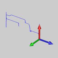
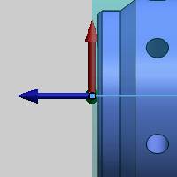
All axes now point in the proper direction for a Mill Turn job, but we want our machining origin to be zeroed at the face of the part and not the stock. Next we adjust the origin location.
Modify the Origin using the Enter Origin Method
-
Before modifying the origin, we change the viewing orientation. Press Ctrl+1to select the Front view.
-
Under Origin, clickEnter Origin.
-
Next to X, click the down arrow one time to change the X-value to 4.000.
Note that we are changing the X-axis value because our machining origin Z-axis is aligned with the X-axis of theWCS (CAD origin). The Enter Origin values are in reference to the WCS.
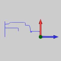
The machining origin updates to the frontface of the part (instead of the front of the stock). The following image uses the wireframe view to better show the new machining origin location.
Define the Work Offset Parameters
-
Under Other,click the Work Offset button.
-
In the Work Offset dialog box, notice that Work Offset #1is selected by default. We use this offset number for Machine Setup1.
-
Update the Z value to5.00.This defines the distance from the virtual machine zero to the machining origin (in Z).Thisvalue is used for simulation purposes.
-
Update the Subspindle Zvalue to 5.00.
This defines the distance between the virtual machine zero and the front face of the sub spindle. You use this value to determine the location to which sub spindle moves when transferring the part.(This value is only used for simulation purposes.)
Important: The PartPickup Position parameter in the Part Transfer MDI command may need adjusted based on the value defined (Subspindle Z).
-
Click OK to close the dialog box.
Define the Clearance Settings
-
Click the Clearancebutton.
-
Notice in the Clearancedialog box that the Auto checkbox is selected under Stock Bounds.
Because our stock and machining origin are already properly defined, the Stock Bounds parameters are automatically detected and populated.
Important: The software automatically calculates the clearance (Stock Bounds) settings based on the stock geometry and the machining origin location and orientation. For this reason, you should define the machining origin before modifying the clearance settings, as the Stock Bounds parameters may not be correct otherwise. The software automatically sets values in the CAM Wizards based on the values in the clearance dialog box.
-
Notice the Clearancesettings for Face, Diameter,and Internal Diameter.
-
You can click in the box for each of these values to update the image in the dialog box to show where these clearance values apply.
-
Change the Face value to 0.500.
-
Change the Diametervalue to 0.500.
-
Click OK to close the dialog box.
Machine Setup 1 is now completely defined.
Part 5) Define Machine Setup 2
Because we already added the second machine setup to the job, we can now define the second machine setup. For the remainder of this example, rotate the model to view the back side of the part.
Select the Machine Setup and Spindle
-
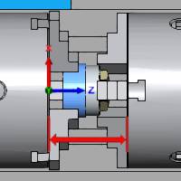
In the Machine Setup window, click the downarrow next to Machine Setup - 1 and click MachineSetup - 2.
We use this machine setup for all features that are created to machine the back half of the part model (on the sub spindle). -
Click Right Spindle,as this machine setup is created for the sub (right) spindle.
Set the Machining Origin
-
The Pick Origin box is already selected, so click the point at the center of the model to set the origin location.
The machining origin moves to the selected point.
Modify the Direction of the Machining Origin Axes
Again, we must align the machining origin to use the appropriate direction for each axis.
-
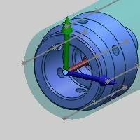
Under Origin,click in the X Axis box, and click the point on top of the model. Be sure to select the point and not the line.
Notice we can select a point (or a vertex)to set the direction of any axis.
-
Click in the Z Axisbox, and click to select the line on the side of model.
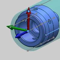
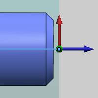
The Z-axis now aligns to the selected entity direction, and our machining origin if properly defined.You should have the same axes directions as shown in the previous image.
Note: We are creating the same alignment for the front and back machinesetups (the X-axis and Z-axis) as shown next. When creating turning features, the part profile is analyzed starting from the XZ plane.
Again, if using sketch geometry for our profiles, they are aligned to the XZ plane.
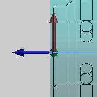
We want this machining origin to be zeroed at the face of the part, so next we adjust the origin location as we did for the first machine setup.
Modify the Origin using the Enter Origin Method
-
Press Ctrl+1to select the Front view.
-
Under Origin, clickEnter Origin.
-
Next to X, click the up arrow once to change the X value to 0.000.
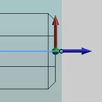
The machining origin updates to the backface of the part.(The Wireframe view is used to better show the new location in the following image.)
Define the Work Offset Parameters
-
Click the WorkOffset button.
-
Next to Work Offset #click the down arrow and select 2.
We use Work Offset #2 for the sub spindle and all features created under Machine Setup 2.
-
Update the Z value to4.00.This defines the distance from the face of the sub spindle to the machining origin.
-
Notice that the Spindle ParkPosition value is already set to 36.00.The software automatically set this value based on the initial position of the sub spindle defined in the machine definition.
The SpindlePark Position defines the distance between the virtual machinezero and the front face of the sub spindle. This determines where the sub spindle sits while machining operations are performed on it.
We use the default value for this example to provide the maximum amount of clearance from other machine components (the main spindle) when working on the sub spindle. Depending on the size of your machine, you may want to change the park position to reduce the amount of sub spindle movement during the program if a large amount of clearance isn't needed.
-
Click OK to close the dialog box.
Define the Clearance Settings
-
Click the Clearancebutton to open the Clearance dialog box.
Because we have properly defined our machiningorigin, the Stock Bounds parameters are automatically set from using the Auto option.
-
Change the Face value to 0.500.
-
Change the Diametervalue to 0.500.
-
Click OK to close the dialog box.
Machine Setup 2 is now completely defined.
-
Click
 to finish the Machine Setup.
Part 6) Additional Job Setup Tasks
Hide the Stock Geometry
It is often helpful to hide the stock geometry while creating machiningfeatures, to make it easier to view the toolpath. You may also want to show the stock quickly for verification purposes. The following steps explain how.
-
In the CAM Tree, right-click Stock,and click Blank.
The stock geometry is hidden from view.
-
To show the stock again, repeat step 1 or use the following step.
-
Click the Stock item in the CAM Tree and notice that the stock geometry temporarily displays in the graphics area. It displays until you click another tree item,such as Mill Turn Tools.You can use this tip to quickly display the stock and confirm a toolpath is correct.
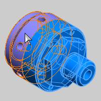
Workpiece Assignment
Workpiece assignment in BobCAM allows you to assign geometry to be used as the workpiece in simulation (usually the model). When you run the Stock Wizard from the Machining Job dialog box, the Workpiece Assignment displays before the stock wizard. This dialog does not display when you open the Stock Wizard from the CAM Tree, as we did in this example. Next we show you how to assign the workpiece from the CAM Tree.
-
In the CAMTree, right-click Workpiece,and click Re/Select.
-
Click to select both halves of the model in the graphics area.
-
Click
 to confirm the selection.
Now that a workpiece is assigned, only the selected geometry displays (as the workpiece) in simulation regardless of what geometry is visible in the graphics area. Be aware that if you hide the assigned workpiece geometry, then the Workpiece button becomes unavailable in simulation. After assigning the workpiece geometry, you can click the Workpiece item in the CAM Tree to highlight the geometry in the graphics area.
Load the Tool Crib
The next step of the process is to load the Tool Crib for the job. More information is provided about loading and mounting tools in the MillTurn Tutorials topic as well as in this Help system.