


Mill Turn Tutorials
Understanding Mill Turn Machines in BobCAM
This section introduces you to the mill turn machines that are installed with the BobCAM software. These machines are used for all examples in the system and knowing how to program mill-turn jobs starts with understanding the correlation between your physical machine and the virtual machine in BobCAM.
Note: Mill Turn is synonymous with turn milling, multitasking, lathe with live tooling, or 3-5 axis lathes.
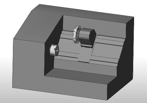
BC 1T 1S
This machine is a common mill turn configuration with a single turret (tool-holding device) and a single spindle (workpiece-holding device). This machine has 3-axis or XZC machining capabilities and a single submachine (work zone). The ability to mount live tooling to the turret is what separates this mill turn machine from a standard 2-axis lathe.
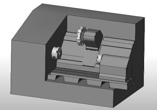
BC 1T 2S
Another common mill turn configuration uses a single turret and two spindles. This machine has 3-axis or XZC machining capabilities and two submachines (work zones). This machine configuration is beneficial because it includes a subspindle (with linear travel), so you can transfer the part from the main spindle to the subspindle to perform work on the back side of the part, helping to reduce setup time.
BC 1T 2S Y
Similar to the BC 1T2S, this machine uses a single turret, two spindles, and adds Y-axis machining capabilities that allow for more versatile milling that cannot be accomplished on machines without a Y-axis. This multiaxis machine has 4-axis or XYZC machining capabilities and two submachines (work zones).
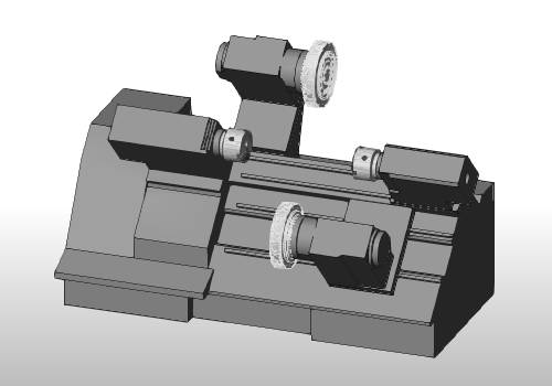
BC 2T 2S
This multiaxis mill turn configuration uses two turrets and two spindles and adds Y-axis machining capabilities to the upper turret only. This machine has 4-axis or XYZC machining capabilities and four submachines (work zones). This machine configuration is extremely versatile because you can mount tools to a second turret, and both turrets can work on either spindle.
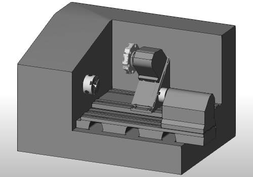
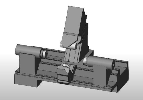
BC 2T 2S 5X
This multiaxis machine contains two tool-holding devices, one turret and one milling spindle/head, and two spindles. This machine allows for 5-axis or XYZBC machining capabilities with the addition of the milling spindle. This machine configuration is highly desirable for its multiaxis capabilities and four submachines (work zones).
Programming CAM Features
Turning
Turning profiles are drawn in the XZ plane of the machining origin (work offset) that you define in the Machine Setup.
Face Milling and Drilling
For face milling or drilling work (Z-axis), you program just as you would for any mill job, where the tool is parallel to the Z-axis of the machine setup (work offset). The following images show a Mill 2 Axis Feature and a Mill Drill Hole feature (set to Standard Drill), in which no special handling is needed.
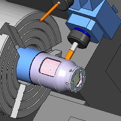
Cross Milling and Drilling
For cross milling work (X-axis), you use index systems, wrapping groups, or the rotary feature, and for cross drilling work you use the cross drilling or multiaxis drilling types. The following images show a Mill 2 Axis feature created under a Wrapping Group to cut the wrapped pockets and a Mill Drill Hole feature set to Cross Drill.
Y Axis Machining
No Y-axis
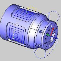
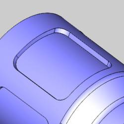
The pocket shown next can be machined without Y-axis machining capabilities. (In BobCAM, this type of pocket is machined using a Wrapping Group.)
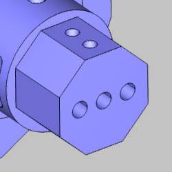
All holes shown next also do not require Y-axis movement. (The front holes are machined with Standard drilling and the top holes are machined using Cross drilling.)
Y-axis Machining
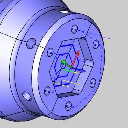
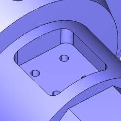
The pocket (and holes) shown next require Y-axis machining capabilities. (The pocket here is machined using an Index System and the holes can be drilled using one of two methods. You can either use Multiaxis drilling, or you can create an Index System and then use Standard drilling.)
Tool Orientation Differences
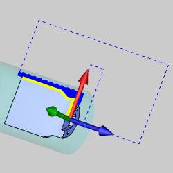
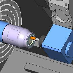
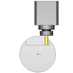
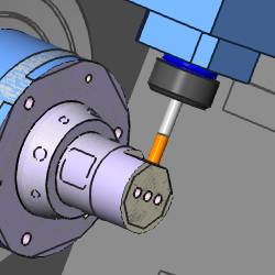
Machining flat areas, for example a hex on the front of the part as shown in the following images, generally can be achieved with or without Y-axis machining capabilities. The difference here is the tool orientation determines how these flat areas can be machined. On Y-axis machines, you can cut with the tool parallel to the X-axis so you are cutting with the bottom of the tool or you can cut with the tool parallel to the Z-axis. On machines without a Y-axis, however, the tool must be parallel to the Z-axis, so you are cutting with the side of the tool.
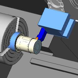
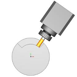
The following image shows machining flats on the front face that doesn't require Y-axis movement. (Machines with a Y-axis can also perform this type of machining, but can do it in two ways: fixed C-axis with XY movement or fixed Y-axis with XC movement.)
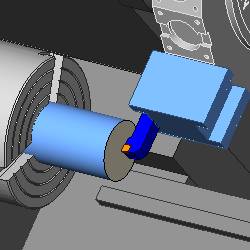
The next image shows another option for machining these flats that can only be accomplished with Y-axis capabilities.
Mill Turn Job Setup
Creating Mill Turn jobs starts with adding a Mill Turn job to the CAM Tree, assigning workpiece geometry, creating stock, and defining one or more machine setups. The following tutorials explains the entire process for the Mill Turn Example 1 example part. (The Mill Turn Example 1 tutorial starts with all of this information already defined.)
Written Tutorial
Mounting Tools in the Tool Crib
Another important part of creating Mill Turn jobs is loading the Tool Crib. There are two methods to use when creating Mill Turn jobs. You can either mount all tools in the tool crib before creating machining features (ideal scenario), or you can mount the tools in the tool crib as you create your machining features. These tutorials show how to load the tool crib before creating machining features, but the information applies to either method.
Written Tutorial
For detailed examples of all Tool Crib mounting parameters, view the Modifying Mounting Parameters example.
For complete descriptions of using the Tool Crib and all parameters found in it, view the Mill Turn Tool Crib topic.
Creating Mill Turn Features
Machine a Complete Mill Turn Part
To learn how to machine an entire mill-turn part in BobCAM, view the Mill Turn Example 1 topic. This example file provides a complete written tutorial as well as videos of the steps performed.
Mill Turn Drilling Focus
To learn more about drilling in Mill Turn jobs, view the Mill Turn Drilling Example 1 topic. This tutorial covers all three drilling types, Standard, Cross, and Multiaxis using a single part. This example provides more details about hole drilling than the Mill Turn Example 1 tutorial.