


What's New in BobCAM For SolidWorks V13
![]()
From Good to Great: BobCAM for SolidWorks V13 Evolves the Workflow
New Built-In CAM Wizard
As shown above, the brand-new CAM Wizard is now built directly into the side panel, giving you a streamlined, modern workflow like never before. Unlike previous versions where you had to fully set the parameters and compute blind without seeing a visual, you can now set up your toolpaths while keeping full visibility of the graphics area — see exactly what you're creating in real time
Even better, the Mill 2-Axis, Lathe, and Wire EDM toolpaths auto-compute on the fly while you're building the feature. For the other toolpaths, you can simply click the "Compute Toolpath" icon button located at the top right of the CAM wizard to see the toolpath changes in the graphics area. That means faster setup, instant visual feedback, and the freedom to make adjustments on the spot.
No need to worry about the visual change of the UI for existing customers. The workflow remains the exact same as the previous CAM Wizard. You will have the same tabs to go through and the same"Previous", "Next", "Finish", "Compute/Finish" and "Cancel" buttons at the bottom to click through the whole wizard.
This is the biggest UI upgrade in
CAM Contextual Help: Less Confusion, More Production
Learning the CAM Wizard just got way easier in
Now, as you build your toolpaths, just hover your mouse over any parameter in the CAM Wizard. Instantly, you’ll get a helpful pop-up with:
A visual image of what the parameter does
A short, easy-to-understand description
A link to full documentation in the Help System
This makes it simple to understand every setting without ever leaving the workflow.
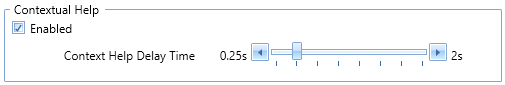
Need more control? You can tweak the pop-up delay, or turn the feature on/off completely, by going to:
File > Settings > System > User Interface > Contextual Help
You’ll also find a handy toggle in the bottom-right corner of the software to only use the help when you need it.
Whether you’re a new user or a seasoned pro, Contextual Help makes programming faster, clearer, and gives you more confidence knowing that you are applying changes you want without guessing.
Sneak Peak: Other Enhancements with Big Impact
New CAM Toolpath Parameters
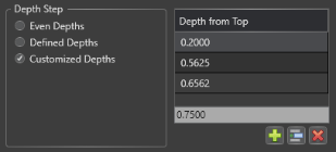
In Mill 2-Axis, you now have full control over your cut depths with the brand-new "Customized Depths" option. Rather than sticking to uniform depths, you can manually define each step exactly how you want it — perfect for using larger depths at the top of the profile and smaller depths at the bottom for precision control.
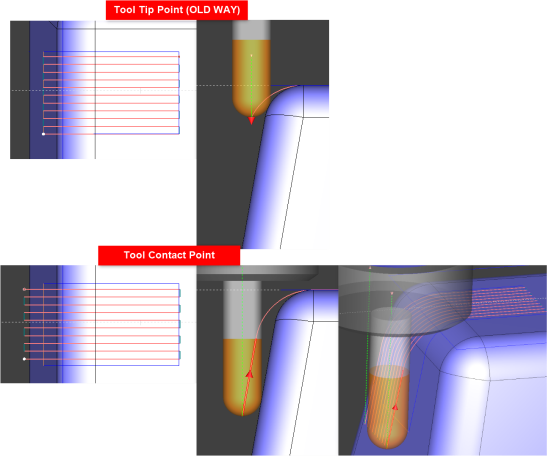
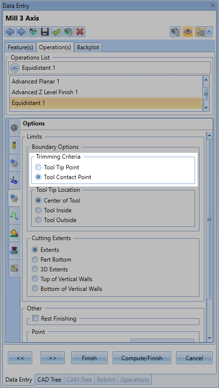
For Mill 3-Axis, Setting up Boundary constraints for the Operations just got a lot easier! The all-new "Boundary Options - Trimming Criteria" gives you a smarter, more accurate way to define machining areas. With the options of "Tool Tip Point" (Old Method) or "Tool Contact Point", you are able to easily cut along 3D surfaces in any X, Y, or Z direction. Instead of manually calculating and adjusting the boundary to where the tool hits, just let the system calculate it for you. The result? Your toolpath follows the actual contact point of the tool rather than over or under traveling, making setup faster and avoiding edge violations.
You’ll also see major gains in the Flatlands Operation, now upgraded with features like optimal XY machining angle, multi-pass depth control, and even an automatic single-pass strategy for thin areas. Combined with a smarter outside-in cutting order, these changes improve surface finish, tool life, and programming efficiency across the board.
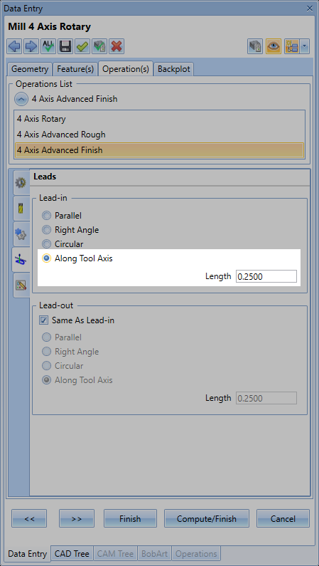
And for those working in 4-axis, the Advanced Finish operation just got a big boost with a new "Along Tool Axis" lead-in/out option. This gives you more control over how your tool enters and exits locking the tool orientation to the rotary axis, especially in complex geometries — reducing marks and improving part quality.
Comparison Table
| Feature | | |
|---|---|---|
| Toolpath Calculation | No real-time feedback; fewer automation options | Auto-compute toolpaths and compute while building the feature to reduce clicks and give instant feedback |
| Toolpath Help | Relied on external online help to navigate out of the software | Contextual help now built into CAM Wizard — hover for instant images, tips, and help page links; learn as you program |
| CAM User Interface Navigation | External CAM Wizard dialog blocking view of the graphics area. Fully setup ALL parameters to compute the toolpath. | Compute as you go CAM Wizard. Modern, panel-based CAM Wizard keeps graphics visible, collapses sections, and feels intuitive |
These upgrades are just some of what makes
FULL List of New Features
User Interface
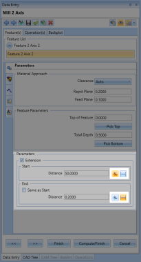
The buttons for the Distance parameter in the Extensions are now more clearly defined to easily distinguish between a percentage value  and a absolute distance value
  . With the percentage toggle enabled, if a value of 50 is set with a tool diameter of 0.5 inch, the extension distance will be 0.25 inches. With the absolute distance toggle enabled, if a value of 0.25 is set, the extension distance will be 0.25 inches regardless of the tool diameter.
New CAM Wizard
The brand-new CAM Wizard is now built directly into the side panel, giving you a streamlined, modern workflow like never before. Unlike previous versions where you had to fully set the parameters and compute blind without seeing a visual, you can now set up your toolpaths while keeping full visibility of the graphics area — see exactly what you're creating in real time
Even better, the Mill 2-Axis, Lathe, and Wire EDM toolpaths auto-compute on the fly while you're building the feature. For the other toolpaths, you can simply click the "Compute Toolpath" icon button located at the top right of the CAM wizard to see the toolpath changes in the graphics area. That means faster setup, instant visual feedback, and the freedom to make adjustments on the spot.
No need to worry about the visual change of the UI for existing customers. The workflow remains the exact same as the previous CAM Wizard. You will have the same tabs to go through and the same"Previous", "Next", "Finish", "Compute/Finish" and "Cancel" buttons at the bottom to click through the whole wizard.
This is the biggest UI upgrade in
The Flow of the CAM Wizard
Components of the CAM Wizard
Top Command Bar
This Command Bar provides a quick way to access and adjust additional settings for the CAM Wizard. Use this bar to navigate the wizard, save default parameters, Compute Toolpath, and adjust the Navigation Tree.
These are the settings from left to right:
 Previous - Go back a previous page
 Next - Go forward to the next page
 Apply to All Operations - Apply parameters on current page to all other Operations with the same parameters
 Save Defaults - Dave Default Parameters to a template. Choose which Operations you want to save as well as if you want to save the feature page information (eg. Rapid/Feed Plane).
 Finish - Finish the CAM Wizard by closing out of the wizard and retaining all information without computing toolpath
 Compute/Finish - Finish and Compute the toolpath for the feature. This closes the wizard.
 Cancel - Close out of the CAM Wizard without retaining any change you made to the feature
 Compute Toolpath - Compute the toolpath of the currently active Operation you have selected in the Navigation Tree. The CAM Wizard will remain opened
 Enable/Disable Preview - Blank/Unblank the currently active Operation in the Navigation Tree
 Show/Hide Navigation Tree - Show or Hide the Navigation Tree
Collapse Navigation Tree - Collapse all items in the Navigation Tree
Expand Navigation Tree - Expand all items in the Navigation Tree
Switch Transparency - Switch between the Navigation Tree having a background of making it transparent
Main Pages
These pages contain all the parameters for the feature.
These are the pages listed from left to right:
Geometry - This page is used to select geometry for the feature
Feature(s) - This page contains the; Parameters page, Machining Strategy page, Tabs page, Posting page, and Multiaxis Post page. Setup initial parameters, the Operations you want to use, if you need tabs, and adjust any post settings for the g-code.
Operation(s) - This page contains the; UI Choice page, Tool Definition page, Patterns and Parameters page, Leads page, Options page, Links page, Corner Types page, Machine Sequence page, Advanced Feedrates page, and MDI page. This is the "meat & potatos" of the CAM Wizard. Setup all the main parameters of each Operation on this page from the tool used to the stepover, allowance, leads, number of steps and so much more...
Backplot - This page allows you to simulate the motion of the tool while still inside the CAM Wizard to give you a good idea what the toolpath will look like. Just pick the Operation you want to view and hit the Play button. Note: For more detailed simulation, click "Start SImulation" in the Milling/Turning/Wire EDM/Mill Turn tab at the top ribbon to load our full simulation.
Property Pages
The property pages are the children of the main pages. These pages show up as tabs on the left-hand side of the CAM Wizard. They section off the data into segments to make it easier to work through. You will notice a similar naming convention for these pages from the previous versions of the software.
These are the pages listed from left to right:
Feature(s) (Main Page):
Parameters - Setup general parameters for the Operation like: Clearance, Rapid, Feed Plane; Top of Feature, Total Depth; Extensions
Machining Strategy - Setup any number of Operations you want to use in the Feature.
Tabs - Add tabs to your profile to hold the stock in place. Primarily used for Mill 2-axis Profiles with CNC routers
Posting - Gives more control of the g-code posting modes and parameters such as defining: Work Offset number; Posting Mode and Submachine selection (For Mill-Turn)
Multiaxis Post - Give more control of the g-code posting sequence and parameters such as defining: Angle Pair solutions; Machine Limits; Pole Handling; Tool Repositioning; setting TCP or other Move List Coordinates
Operation(s) (Main Page):
- UI Choice - Set "Standard UI" or "Advanced UI" to expose all of the ModuleWorks toolpath options available. This page is only available for Operations that have ModuleWorks User Interfaces (Eg. Advanced Rough, Equidistant).
Tool Definition - Setup the tool used for the Operation, open the Tool Crib, and adjust dimensions if needed.
Patterns and Parameters - Setup all the main parameters of the Operation such as defining: Cut Pattern/Direction; Depth of Cut and Stepover; Allowance; Top/Bottom of Job
Leads - Setup the Entry/Exit type as well as the Lead-in/out for the Operation
Options - Setup parameters like: Cutting Extents and tool point of calculation
Links - Define how the toolpath links between cuts
Corner Types - Define how to handle corners on profiles: Rounded, Sharp, Loop Radius, etc...
Machine Sequence - Define how the order of multiple geometries are processed.
Advanced Feedrates - Gives more control over the feedrates and provides options such as: Convert Rapids to Feeds; Lead-in/out feedrate percentage; Corner Slowdown; Adaptive (Volume Based) or Radial Chip Thinning Feedrates
MDI - Define and Setup custom M and G Code commands used before or after a tool change, or after an operation. Examples could be: Adding Optional Stop after Operation; Adding a Part Transfer routine for a Mill-Turn machine; Adding special Macro B programming calls
Navigation Tree
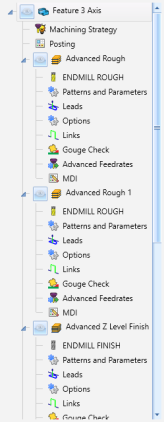
The Navigation Tree and used to quickly move through the CAM Wizard providing a easy visual of all the pages in the feature. Simply click on the icon/title of the page that you want to go to and the CAM Wizard will load that page.
The navigation tree also has the ability to Blank![]() or Unblank
or Unblank![]() a toolpath operation. Blanking out a operation can help you focus on a specific operation while editing the parameters so that the other toolpaths are not in the way. Alternatively, if you always want this behavior of blanking out Operations and only viewing the toolpath of the current Operation you are working on, you can go to Settings > System > CAM and enable "Auto Blank New Items". This will automatically balnk out Operations as they get created. Then, whatever Toolpath Operation is actively selected in the Navigation Tree will be shown in the graphics area.
a toolpath operation. Blanking out a operation can help you focus on a specific operation while editing the parameters so that the other toolpaths are not in the way. Alternatively, if you always want this behavior of blanking out Operations and only viewing the toolpath of the current Operation you are working on, you can go to Settings > System > CAM and enable "Auto Blank New Items". This will automatically balnk out Operations as they get created. Then, whatever Toolpath Operation is actively selected in the Navigation Tree will be shown in the graphics area.
You might also notice that the Navigation Tree will sometimes give you a "Need to compute toolpath!" flag (shown here:  ). Mill 2-axix, Lathe, and Wire EDM operations will compute automatically. However, the Mill 3-Axis and Mill 2-Axis Adaptive Roughing Operations will need to be computed by either pressing the Compute Toolpath icon in the Top Command Bar to stay in the CAM Wizard or hitting "Compute/Finish" at the Bottom Command Bar to exit the CAM Wizard.
You can also control the whether or not you even want to see the Navigation Tree by clicking the Show/Hide Navigation Tree (pictured in the top left here: ) button in the Top Command Bar. Use the drop-down arrow of this button to collapse/expand the Navigation Tree items and toggle off and on the background transparency of the Navigation Tree.
Bottom Command Bar
This bar serves as the main navigation and compute tool of the CAM Wizard. Similar to the CAM Wizard in the previous versions of the software, this command bar allows you to progress through each page, finish and close the Wizard without computing any additional toolpath, Compute and close the CAM Wizard and cancel out of the Wizard without saving any information.
These are the buttons from left to right:
 Previous - Go back a page
 Next - Go forward to the next page
 Finish - Close the CAM Wizard and save all information. The Feature will be created in the CAM Tree without any additional toolpath being computed
 Compute/Finish - Close the CAM Wizard and compute all toolpath. The Feature will be created in the CAM Tree with all Operations getting computed
 Cancel - Close the CAM Wziard and DO NOT save any data at all. If you started a new Feature, no CAM Tree feature would get created. If you are editing an existing Feature, no changes will be made to the parameters and it will return to the original state it was in before entering into the Feature.
Contextual Help for CAM
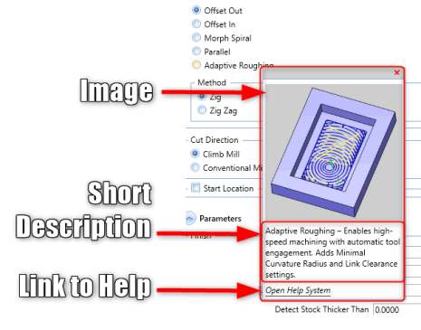
The new version brings the Contextual Help pop-up to the CAM parameters! In the previous version these pop-ups are shown in the CAD functions when you hoover over a parameter. Now, in the new version, this Contextual Help shows up in the new CAM Wizard. Simply hoover your cursor over a parameter name and wait for the Contextual Help to pop-up (See below)
These are the sections from top to bottom:
Image - An image showing an example of the parameter sometimes with visual aids to help understand where the parameter is used in the toolpath
Short Description - A short description describing what the parameter is
Open Help System - A link that opens either the Online Help System or local Help System to the page the parameter is.
With the new version comes a new setting for the Contextual Help called the "Context Help Delay Time". This allows you to setup the delay that the contextual help will pop-up when you hoover over a parameter. Choose between 0.25 seconds - 2 seconds delay.
General
Easier Access to Pack2Go / UnPack
You can now Pack2Go or Unpack inside the CommandManager BobCAM tab to provide easier access to these functions.
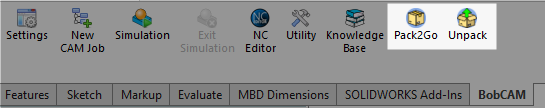
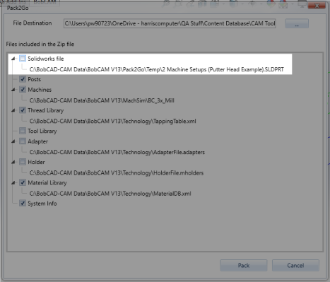
Pack2Go: Exclude The Main Part File From the Pack2Go Zipped Folder
Inside the Pack2Go dialog, it is now possible to uncheck the
Settings
The Line Thickness Scale Option in the Print dialog now retains the previously held value when closing and reopening the software.
CAM
Tool Highlighted color changed in the Mill-Turn tool crib to clearly see both the tool holder and tool insert
CAM
General
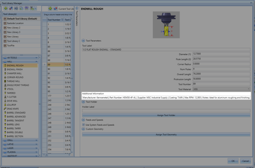
Additional Information Parameter for Tools
There is a new text field when you are editing a tool in the Tool Library to set up "Additional Information". Now store info about the tool such as Manufacturer, Part Number, etc...
Example Additional Information:
Manufacturer: Kennametal | Part Number: HEM50-4F-AL | Supplier: MSC Industrial Supply | Coating: TiAlN | Max RPM: 12,000 | Notes: Ideal for aluminum roughing and finishing.
Auto Rename All Names In The CAM Tree
There is a new option when you right-click on the Machine Setup or Job in the CAM Tree to "Auto Rename All". This tool finds any names that are identical and appends the name with a number so that each name is unique. The new CAM Wizard does already auto-rename the Operations. However, this can be used if you are opening an existing file.
New ModuleWorks MDES File Format
An MDES file is a machine description file that defines the kinematics, geometry, and behavior of CNC machines for use in ModuleWorks-powered simulations. The MDES format is a proprietary file type developed by ModuleWorks. It is primarily used for defining machine descriptions within CAM (Computer-Aided Manufacturing) environments. MDES files contain all the data necessary to describe a CNC machine’s kinematics, structure, and behavior that are essential for machine simulation and collision detection during toolpath verification.
An MDES file includes:
Machine Structure – Definition of machine components (axes, tables, spindles, turrets, etc.)
Kinematics – Motion relationships between axes (rotational, translational, linear axes)
Geometry – Simplified 3D models of machine parts used for simulation
Limits & Constraints – Axis travel ranges, speeds, and restrictions
Tool Holder & Workpiece Setup – Information needed for accurate simulation and collision checking
Usage
ModuleWorks-powered Simulation – Ensures realistic movement of CNC machines during virtual toolpath execution.
Collision Detection – Prevents tool crashes by analyzing tool, holder, and machine interactions.
Verification & Training – Provides a safe environment to test machining strategies before running them on a physical machine.
To learn more about this new file format, navigate to the official ModuleWorks website: https://www.mdes.info/en/
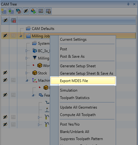
To export a CAM Job as a MDES file type, in the CAM Tree, right-click on the Job name and select, "Export MDES File".
Mill 2 Axis
General
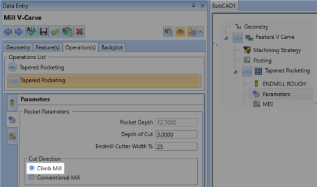
The "Tapered Pocketing" Operation found in the "Mill V Carve" feature has a new option to set the Cut Direction to "Climb Mill".
There is now an arrow that displays in the middle of each toolpath entity when backplotting. The size of this arrow as well as disabling/enabling it can be found in the Backplot dialog under "Show Direction Arrow".
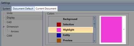
There is now a different color for highlighting the current toolpath you have selected to make to easier to differentiate between the selected toolpath and the other toolpaths showing in the graphics area.
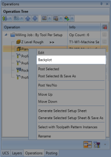
You can now right-click on an Operation in the Operation Tree and get to the "Backplot" dialog from this tree.
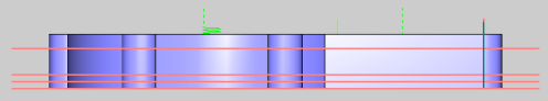
Customized Depths - Vary The Depths Between Each Depth Cut
You can now setup variable depth of cuts in the Mill 2-Axis Operations. This gives you the ability to be able to setup larger gaps towards to top of the part and smaller gaps at the bottom when trying to finish the part or any variation in between the top and bottom of job.
These are the buttons from left to right:
 Add - Add a depth cut. The default value splits the distance between the previous depth cut and the bottom of job
 Insert - Insert a depth below the selected Depth. The default value splits the distance between the previous depth cut and the next depth cut
 Move Up - Deletes the selected depth cut
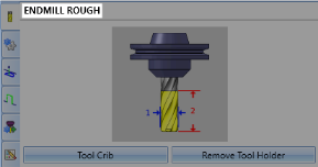
The full name of the Tool Type is now displayed in the top left of the tool page in the CAM Wizard.
Hole
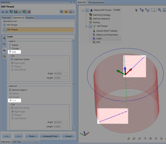
Mill Thread
You can now select a "Line" lead in/out for the Mill Thread Operation Leads.
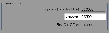
Facing
There is now an additional parameter in the "Mill Facing" Operation that allows you to setup the Stepover based off of distance, rather than just by percent of tool diameter.
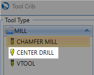
Chamfer Mill
You can now select the "Center Drill" Tool Type for the Chamfer Mill Operation.
3 Axis
General
Tool Tip Point and Tool Contact Point
New boundary trimming options—Tool Tip Point and Tool Contact Point—have been added to the Advanced Planar, Advanced Z Level Finish, and Equidistant toolpaths, giving users finer control over how toolpaths are trimmed to containment curves. These options allow users to choose whether the boundary is respected based on the position of the tool’s tip or its contact point with the surface. This enhancement is especially useful when working near containment edges, improving precision and efficiency when processing cusps and surface transitions, especially in triangle mesh-based toolpaths.
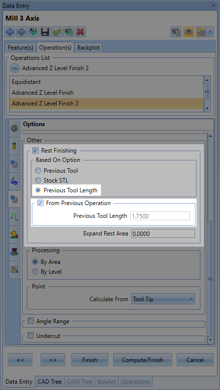
Rest Finishing By Previous Tool Length
A new By Tool Length option has been added to the Rest Finishing settings in Advanced Z Level Finish, Advanced Planar, and Steep Shallow operations. This enhancement detects and removes remaining material that previous tools couldn't reach due to limited stick-out or flute length. By dividing the toolpath into zones based on the previous tool’s usable length, this feature improves surface quality, enhances feed control, and ensures better access to deep or restricted areas without manual cleanup.

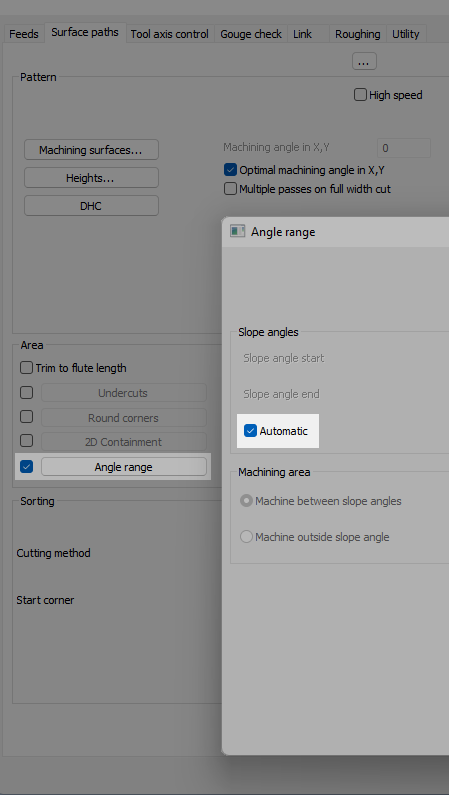
Automatic Angle Range Detection for Barrel Tools
A new Automatic option has been added to the Angle Range section for the Advanced Z Level Finish, Advanced Planar, and Equidistant toolpaths (Advanced UI only). When using supported barrel tools—Lens, Double Profile, and Tangent to Shaft—this enhancement intelligently detects which areas of the part can be machined in 3-axis and automatically sets appropriate slope angles based on the tool’s geometry. This helps improve surface quality while reducing setup time and user input. Toolpath focus adapts based on the tool and strategy: walls are favored in Advanced Z Level Finish, while floors are prioritized in Advanced Planar and Equidistant.
Advanced Rough
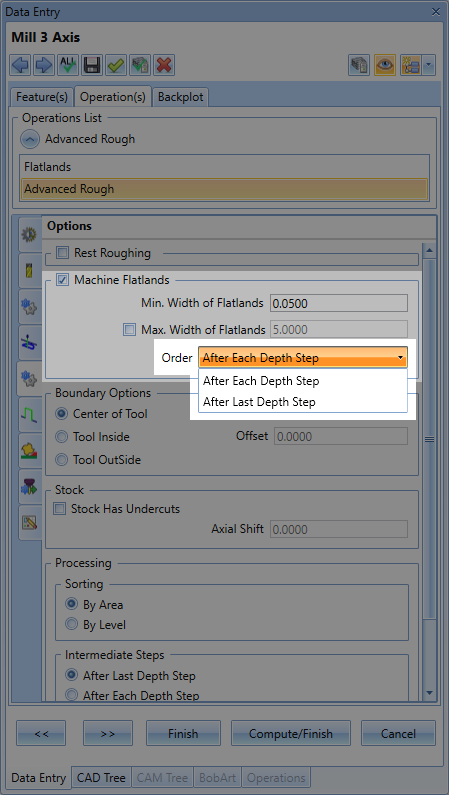
After Each Depth Step and After Last Depth Step
A new Order option has been added to the Flatlands feature within the Advanced Rough operation, giving users greater control over when flat areas are finished during roughing. Users can now choose to machine flat regions either After Each Depth Step, where flats exposed at each step are cleaned up immediately, or After Last Depth Step, where all flat areas are finished in one pass after full roughing is complete. This flexibility improves machining efficiency and part quality by allowing Flatlands to be applied exactly when needed.
Optimized Level Based Ordering
Advanced Roughing now features optimized level-based ordering, reducing unnecessary retracts and links between regions. By improving the way toolpath levels are processed, this enhancement shortens machining time and promotes smoother, more efficient motion throughout the operation.
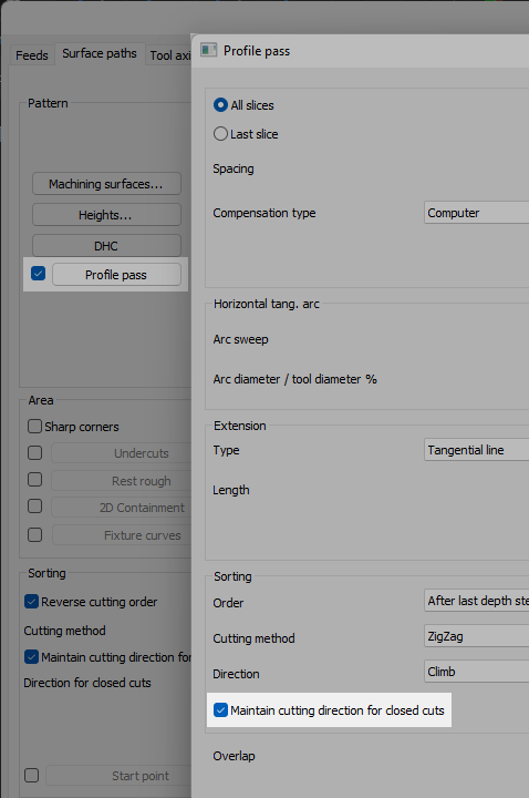
Maintain Cutting Direction for Closed Cuts
The Advanced Roughing toolpath now includes a Maintain Cutting Direction for Closed Profile Passes option, giving users greater control over tool engagement in closed-loop regions. When enabled, the system preserves the selected cutting direction—climb or conventional—throughout each closed profile. For open areas, a zig-zag approach is still used to optimize link lengths and reduce machining time. This blend of precision and efficiency enhances both part quality and cycle performance in Advanced UI workflows.

Advanced Planar
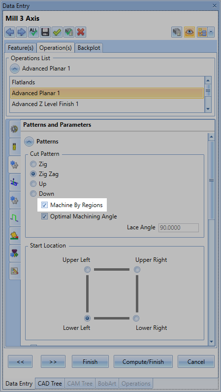
Machine by Regions
The Parallel Cuts pattern now supports Machine by Regions, a new ordering method that completes one region at a time before moving to the next. This approach eliminates unnecessary engages and retracts within a region, resulting in improved surface quality and smoother motion. Offered alongside the traditional shortest path option, this feature gives users more control over toolpath behavior in complex geometries.
Equidistant
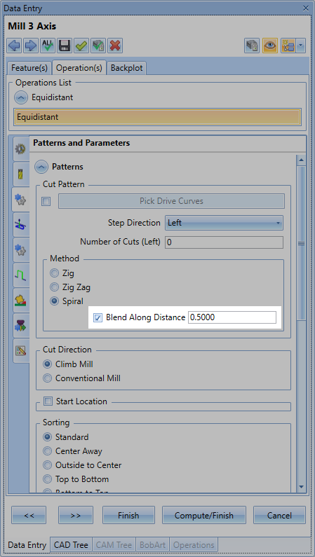
Blend Along Distance
The Equidistant operation now includes a Blend Along Distance option for Spiral patterns, offering a new way to create smooth, continuous motion across the surface—similar to Spiral behavior, but with the flexibility of a Zig pattern. Rather than linking separate passes with abrupt transitions, this option blends between them over a defined distance, creating fluid shifts where one pass transitions into the next. It’s ideal for complex areas where traditional Zig motion may introduce sharp linking moves, delivering improved surface finish and a more refined toolpath across both flat and contoured surfaces.
Flatlands
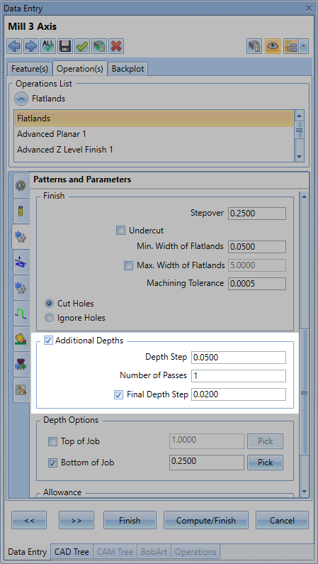
Additional Depths
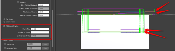
The Flatlands operation now includes an Additional Depths option, designed to improve control when machining thicker stock. Instead of cutting flat areas in a single pass, users can now divide the motion into multiple depth steps for more efficient and safer roughing. This group includes options to define a consistent Depth Step, set a specific Number of Passes, and an option to enable a Final Depth Step to apply a lighter finishing cut at the bottom. These enhancements give users greater flexibility when managing material removal and tool load on flat regions.

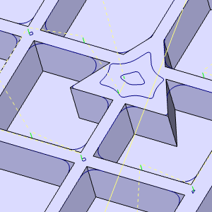
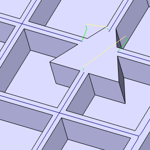
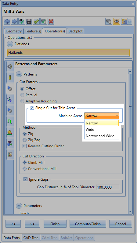
Single Cut for Thin Areas
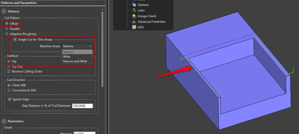
Single Cut for Thin Areas improves toolpath efficiency by applying an optimized algorithm that reduces travel, especially in tight regions where multiple offset passes aren’t needed. This checkbox enables a streamlined approach in areas smaller than the tool diameter, offering three targeted options—Narrow, Wide, and Narrow and Wide. The Narrow option traces along tight regions with a single pass, Wide skips unnecessary cuts and applies shaped offsets to broader areas, and Narrow and Wide combines both strategies. This added control leads to cleaner, faster results in challenging flatland geometry.
| Previous Algorithm | Narrow | Wide | Narrow and Wide |
 |  | 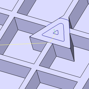 | 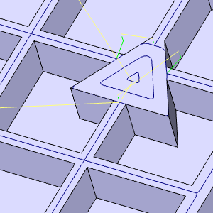 |
Optimal Machining Angle
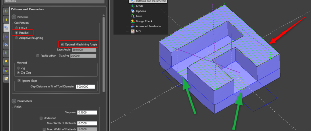
The Flatlands strategy now includes Optimal XY Angle, a powerful toolpath enhancement originally introduced in Planar. This feature intelligently aligns parallel passes with the longest dimension of each machined area, optimizing cut direction for improved efficiency and surface quality. By allowing independent angle adjustments across different regions, it maximizes material removal and minimizes air cutting—bringing smarter, faster machining to flat features with complex shapes.
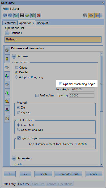
Outside-in Ordering Enhancements
Flatland toolpaths now benefit from an automatic outside-in ordering strategy that optimizes pass direction without requiring user input. By starting from the outer edges and working inward, this improvement reduces top-down engagement on the material surface—resulting in better surface quality and significantly extended tool life. This behind-the-scenes enhancement delivers smarter motion for cleaner, more efficient flatland machining.

V-Carve
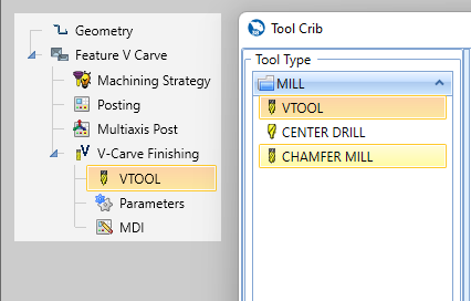
Spot Drill and Chamfer Mill support for V-Carve
The V-Carve toolpath in BobART now supports Spot Drills and Chamfer Mill tools, giving users greater flexibility when selecting tooling for artistic and engraving-style operations. This enhancement expands beyond traditional V-style tools, allowing for more control over edge detail, engraving depth, and finish quality. Whether you're creating decorative features or functional markings, the ability to use these tool types adds precision and efficiency to your BobART workflows.
Rotary Machining
Leads for Roughing
A new Leads for Roughing option has been added to rotary machining toolpaths in the Advanced UI, allowing users to apply lead-in and lead-out motions to roughing operations. These additional moves enable smoother tool engagement and exit, reducing the risk of tool shock and improving material removal quality. This enhancement brings more control and reliability to rotary roughing strategies, especially in complex geometries where clean entry and exit paths are critical.
Leads for Finishing
The Cylindrical or Conical Surfaces pattern in rotary finishing now supports Leads for Floor Finishing, allowing users to apply lead-in and lead-out motions for smoother tool entry. This enhancement offers greater control over the toolpath, reduces tool marks, and can improve surface finish in critical areas. Available exclusively in the Advanced UI, this option adds refinement to floor finishing strategies for cylindrical and conical surfaces.
Fixture / Chuck support
Rotary Roughing and Finishing toolpaths now support fixture and chuck collision avoidance, adding a new layer of safety and precision to rotary machining. Users can select a mesh or model to represent the fixture or chuck, which is then spun and analyzed during toolpath calculation to avoid collisions. An optional offset ensures added clearance and control. This enhancement not only improves confidence and safety during programming but also streamlines CAM integration, particularly when working with complex rotary setups or tight clearances.
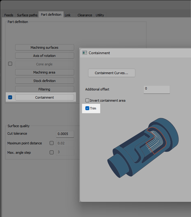
Containment Trim for Rotary Finishing
A new Trim option has been added to the Containment dialog for rotary finishing toolpaths, giving users more precise control over how toolpaths interact with selected boundaries. When enabled, the toolpath is generated as if no containment exists, and then trimmed back to the containment region based on the tool center. This avoids unnecessary toolpath extensions beyond the defined boundary and provides a cleaner finish in critical areas. Ideal for users who want to apply containment boundaries without altering the natural flow of the toolpath, this enhancement offers greater flexibility and refinement for finishing operations.
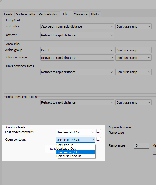
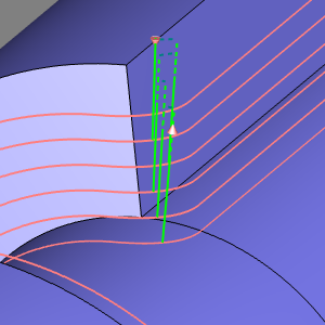
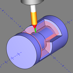
Along Tool Axis Lead
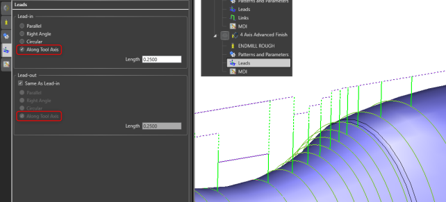
A new Along Tool Axis lead type has been added to the standard UI for Rotary Finishing operations. Previously limited to Parallel, Right Angle, and Circular leads, the updated interface now includes a vertical lead option that moves the tool directly along its axis for entry and exit. This enhancement improves control and flexibility for rotary finishing strategies, especially when working on complex or confined geometry.
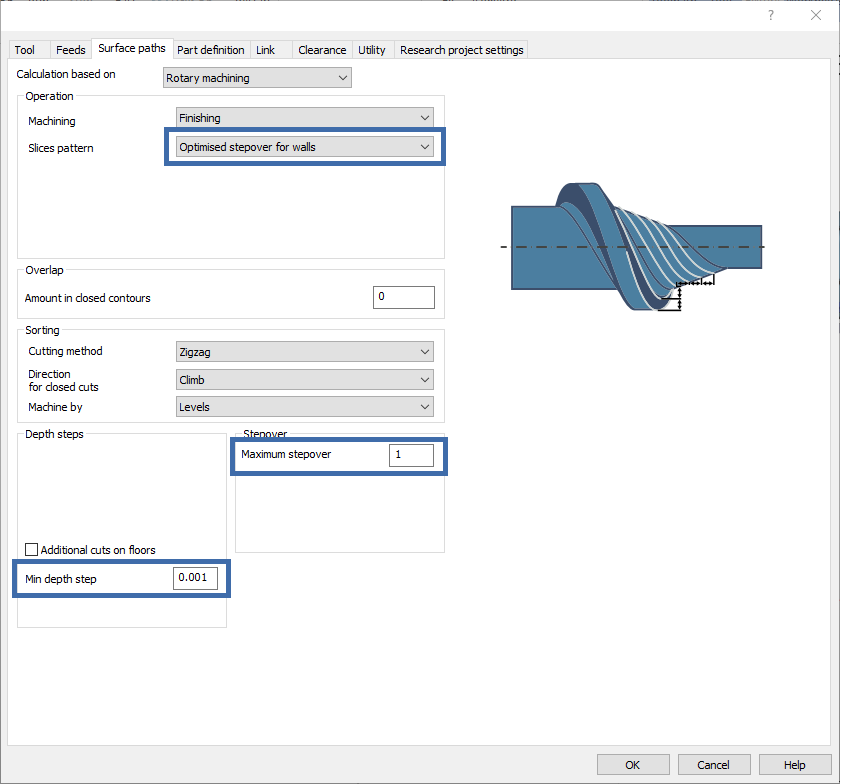
Stepover Optimization for Wall Finishing
Rotary Machining users can now benefit from optimized stepover for walls, ensuring more consistent maximum stepover on curved and slanted surfaces, thus improving precision. Users can also adjust the minimum depth step, reducing the number of required toolpaths and increasing efficiency. Toolpaths are trimmed to focus only on necessary areas, minimizing unnecessary machining.
Turn Milling
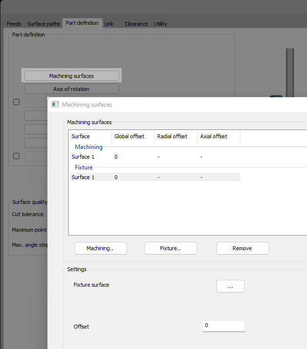
Multi-Geometry Picking and New Fixture Selection
You can now select multiple profiles and fixture geometry for the Turn Milling Operation
Support for multiple Turn Profiles / Machining Surfaces for Turn Milling - gives more flexibility when selecting geometry for the feature
The new enhancement for Turn Milling allows users to select more than one profile or surface for the geometry in the machining surfaces dialog.
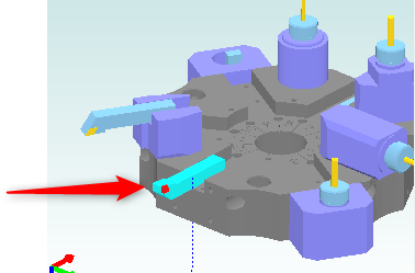
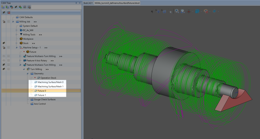
As seen in the image below, you can also select multiple Fixture geometries as well.
Support for Fixtures/Chucks for Turn Milling - improves collision avoidance with Fixtures/Chucks
The new enhancement for Turn Milling allows users to select Fixtures/Chucks for inclusion in the collision avoidance calculations for Turn Milling toolpaths.
The selected mesh/model is spun, and the resulting profile is used to avoid collisions. An offset distance is also provided to give users more control and greater safety.
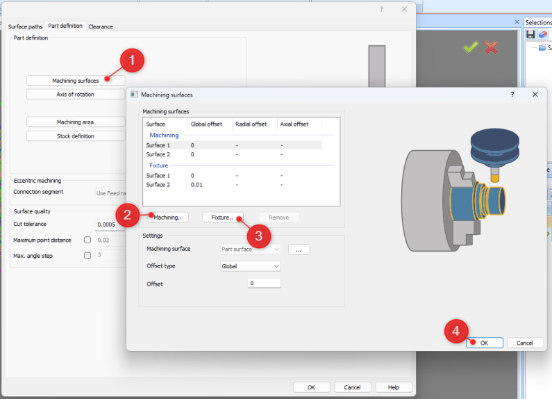
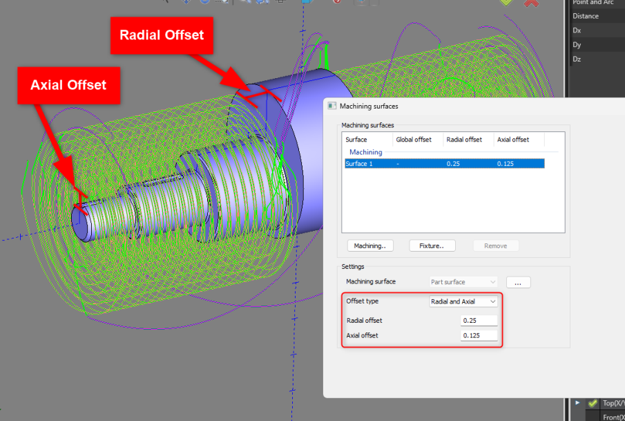
Offset Type - Radial and Axial Allowance
There is a new feature within the new “Machine surfaces” dialog. There is now an option to set an “Offset Type”. This is similar to how you can define an “Offset Type” for your allowance in the Advanced Rough operation for either “Side and Bottom” to set two different offsets depending on if it a wall or floor surface, or “global” to set a universal offset amount for any surface. This Offset type for the Turn Milling operation allows you to define “Global” offset allowance for all surfaces, or “Radial and Axial” for wall surfaces or cylindrical floor surfaces.
Axial and Radial Offsets for Turn Milling - provides greater control of offsets
There is a new option for setting the axial and radial offsets for both the machining geometry and the fixture, in addition to the existing global offset option. This means that users can now define offsets to meet the finishing requirements.
This provides more flexibility and control over leaving the offset material to meet the requirements of the specific finishing job, resulting in an overall better surface finish.
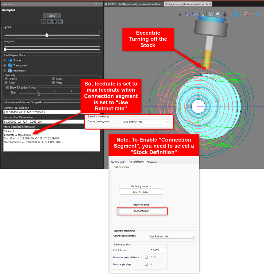
Eccentric Turning - Faster Links
There is a new option on the “Part Definition” page called, “Connection segment”. This allows you to define how you handle toolpath that is not touching the part. It allows you to set “Use Retract rate” to make the tool move at max feed rate when it is air cutting and “Use Feedrate” to keep the old way of moving at the Operation’s defined feed rate.
Faster Links in Eccentric Milling - enhances the feed rate for faster linking
Allows users to generate faster linking moves in roughing toolpaths when performing eccentric milling.
This reduces the overall cycle time of the operation as the tool moves faster when it is not cutting any material.
This new option offers better support for eccentric parts, especially casting, and reduces machining time.
This option is available only when Stock is defined as a Surface.
Deburring
Continuous Toolpath Around Corners
The Deburring toolpath now provides a more continuous toolpath when handling inner or outer corners. No need to set any parameters in the CAM Wizard! The toolpath calculation will automatically handle this.
Corner Arc Support for Chamfer Tools
This new enhancement creates a continuous toolpath around inner and outer corners when using a chamfer mill without any intermediate links for 5-axis deburring.
This reduces the linking motions and hence the overall cycle time for chamfering.
Toolpath enhancements, no UI change
More Rigid 5-Axis Toolpath Motion For Better Surface Finish
Toolpath Calculation improvement for 5-Axis Simultaneous motion. Ensures more 3+2 motion and minimal 5-aixs motion. No need to set any parameters in the CAM Wizard! The toolpath calculation will automatically handle this.
Consolidated 3+2 Behaviour
The common direction algorithm has been enhanced for deburring to ensure a 3+2 orientation with minimal 5-axis movements.
This minimizes undesired 5-axis motions, resulting in safer and more accurate machining.
Links etc. Core Technologies
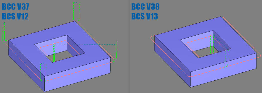
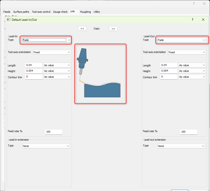
New "Fade" Lead Type
This "Fade" lead type moves slowly away from and towards the machine surfaces. The result is a very small ramp that enables rest finishing strategies to easily engage the material without leaving stepover marks on the workpiece. The main benefit is improved surface quality after tool changes, orientation changes and machine down times.
Fade Lead In/Out – new Lead Type
This "Fade" lead type moves slowly away from and towards the machine surfaces. The result is a very small ramp that enables rest finishing strategies to easily engage the material without leaving stepover marks on the workpiece.
The main benefit is improved surface quality after tool changes, orientation changes and machine down times.
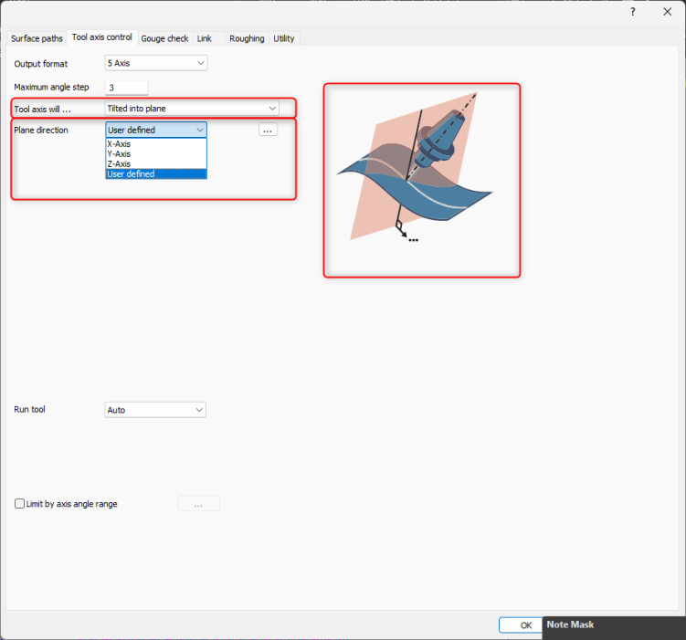
User Defined Plane Direction for Multi-Axis Tool Axis Control
There is a new option called, "User Defined" in the Tilited into plane "Plane direction" drop-down box found on the "Tool axis control" tab for the Mill Multi-axis feature. The "User Defined" option allows you to restrict the tool axis within a user defined plane of motion instead of just the X, Y or Z axis. This is a very specific new feature, but very useful if ever needed.
Using this feature, the tool axis can be restricted in the user defined plane.
Depending on its orientation, either rotary or alternatively tilt can be avoided completely. If the plane normal is aligned with a rotational axis of the machine, it will limit rotational machine movements to that axis.
Benefits: With this enhancement, users can expect fewer machine axis movements for more stable machining.
Select Surfaces To Define Retract Clearance Areas
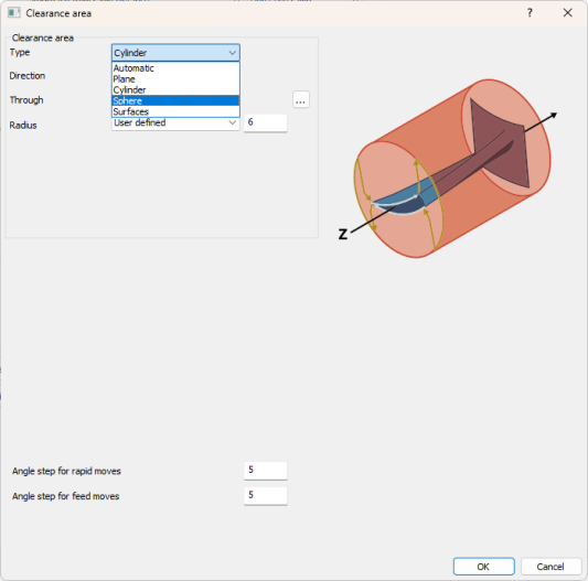
There is a new Clearance Area type for the Mill Multi-axis feature that allows you to set the Clearance Area based of a set of user defined surfaces. Previously, you could select a Plane, Sphere or Cylinder aas a Clearance area. However, in really tight spots on certain models, you sometimes need to be able to select a very specific set of surfaces to retract the tool to. This is where the "Surfaces" type will shine.
This new feature allows the selection of user-defined surfaces as clearance areas. With this feature, toolpaths can be limited to shorter retracts, thereby reducing the overall cycle time while providing more flexibility and control to the user
![]()
![]()
![]()
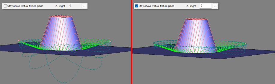
Stay Above Fixture Plane (Sphere Clearance Type)
There is a new option called, "Stay above virtual fixture plane" which is used with the Sphere Clearance Area Type. There are cases where the Sphere retract goes below the desired work area. This new option trims the retract so that the retracts do not go under the part and cause a potential collision. For Sphere Retract type.
Virtual Fixture Plane for Safe Linking
With this feature, users can avoid links that go beyond the defined virtual fixture plane. This prevents the tool from entering dangerous areas.
This feature defines the fixture plane according to a user-specified height so that links are forced to stay above that plane.
Defining the fixture plane reduces the risk of collisions, even on complex machining setups.=
This option is available for Sphere Clearance only.
![]()
Multiaxis Machining
Roughing
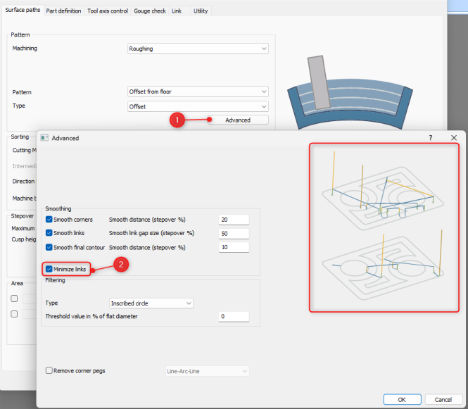
Roughing: Minimize Links (reducing cycle time), Ramp improvement, improves tool engagement, New “Detect thicker than” to avoid toolpath is unnecessary areas, New Clearance options similar to options in “Surface” Ops
The new "Minimize Links" toggle can be found in the "Advanced" button in the "Pattern" section.
This new enhancement reduces the number of ramps in the multi-axis roughing strategy by optimizing the start points for closed contours.
This means that some ramps are removed, and, in these cases, the tool engages from previously cut passes.
This reduces the total cycle time of the operation while increasing tool life.
Toolpath Calculation improvement: Trim Line Ramps
With this improvement, the line ramps are now trimmed to the stock.
This ensures that the ramp length is appropriately defined according to the available stock which in turn reduces the overall engagement time
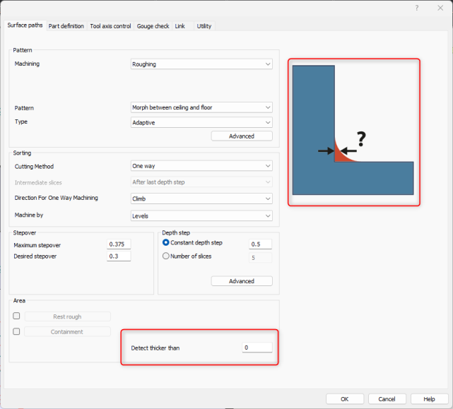
There is a new “Detect Material Thicker Than” option is used to detect only areas thicker than the assigned value. It works similar to an allowance where you set the amount left to be machined with the finishing tool. This gets rid of additional toolpath that is generated in areas where you do not need to cut.
With this new feature, thickness of rest material gets detected considering the preset value. This improves the quality of stock-based roughing operation, as tool does not go into the unnecessary areas.
You can now set more Clearance Area types for the Multiaxis Machining Roughing Operation such as Plane, Cylinder, and Sphere. Previously, you had to manually define the surfaces you want to retract to. For basic retracts, this required additional work of creating surface planes for selection. You now have access to these options directly in the CAM Wizard.
With this enhancement users can define clearance area as plane or sphere or cylinder to handle retracts.
Plane: The planar area is raised above the workpiece at the specified height and in the desired direction. The direction is determined by the direction of the plane normal vector.
Cylinder: The cylindrical area around the workpiece is specified by the radius and desired direction. This may be useful for 4-axis and 5-axis machining operations.
Sphere: The spherical area around the workpiece with a specified radius and desired position. The position can be defined as XYZ coordinates or by an imported point
Wall, Floor and Rest Finishing
Finishing: Barrel Tools; Considered profile section to determine what part of the tool you want to engage the material, Cusp Height option added, Toolpath Extension extends toolpath of closed contours to eliminate cusps at start/ends of toolpath, new Parallel to Floor Surface pattern for Wall Finishing.
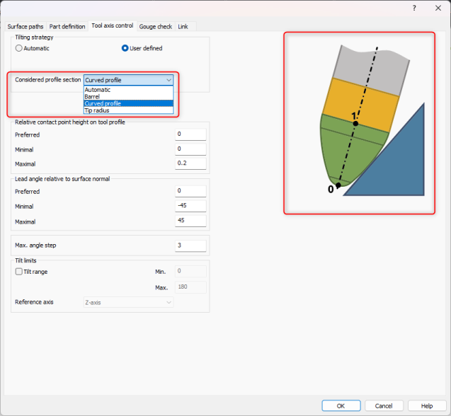
There is a new option for the "Considered profile section" drop-down in the Tool axis control page to control the Curved profile. The picture that highlights the tool in green shows the full area that the tool can engage with the stock. This gives users greater control over the tilting range as well as the tool contact point for operations.
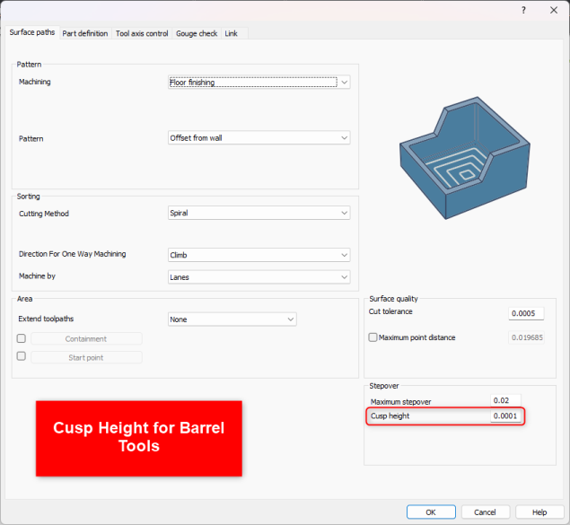
You can now define the Stepover by Cusp Height for the Multiaxis Machining Finishing Operations.
This enhancement adds an option for defining the stepover based on the cusp height for advanced tools, including barrel mills.
With a cusp-based stepover, users can easily set up operations and avoid mistakes in manual calculations
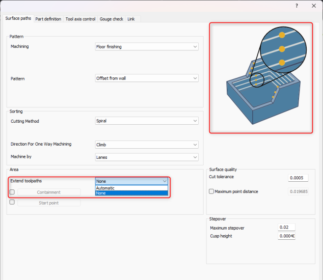
You can now Extend toolpaths for the Multiaxis Machining Finishing Operations similar to how you can extend toolpath in other Operations to extend the toolpath fully off the part.
This feature allows the tool to extend its motion beyond the start and end point of each closed contour. This reduces the size of the cusps at the start and end points, in particular with advanced tools such as barrel tools, and produces clean surfaces.
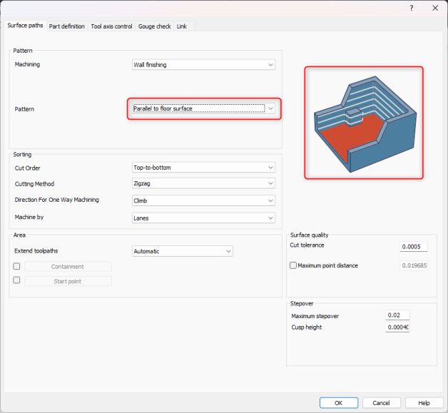
There is a new "Pattern" for the Multiaxis Machining Finishing Operations called, "Parallel to floor surface".
The new floor parallel cut pattern for wall finishing generates slices parallel to a planar floor to ensure that features on the wall do not disrupt the pattern generation.
This introduces a whole new set of geometries that can be machined with less tilting and better surface quality.
Multiblade Machining
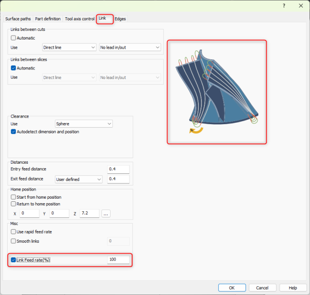
You can now set a "Link Feed rate(%)" for the Mill Multiaxis Multiblade Operation in the Link page.
Lathe
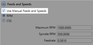
You can now enable “Use Manual Feeds and Speeds” for lathe tools on the tool page. This works similar to the Milling tools. The additional advantage this provides is that is allows you to keep the same manual feeds and speeds that you setup if you want to select the same tool for a different operation. You will not have to redefine the manual feeds and speeds every time you use the tool in a new operation.
Simulation
The improvements target rendering the stock model and also allow for an improved more watertight mesh to export. This new triangulation method leads to significantly faster stock drawing and mesh exports, resulting in improved overall simulation performance. In addition, the new method significantly improves the watertightness of the exported mesh.
New Graph-based Triangulation
This new triangulation method leads to significantly faster stock drawing and mesh exports, resulting in improved overall simulation performance. In addition, the new method significantly improves the watertightness of the exported mesh.
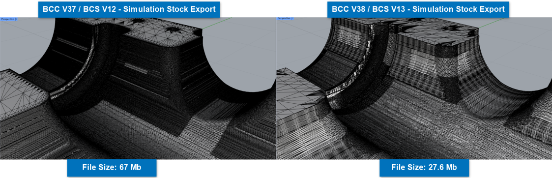
Overall improved wait time in simulation. This is especially noticeable in large stock models and large amounts of toolpath.
Asynchronous Rendering
Rendering calls for highly complex in-process stock can be expensive, affecting the responsiveness of the CAM application.
Asynchronous rendering uses a separate thread to triangulate and render the in-process stock, independent of the simulation thread. This improvement accelerates simulation in play mode by eliminating wait times for in-process stock rendering.
Reduced wait time in simulation load and run.
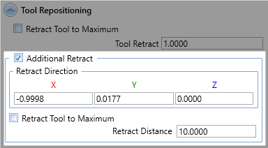
Multiaxis Post page
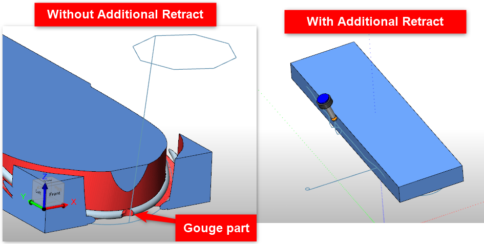
It is now possible to define the "Retract Direction" of the Additional Retract option on the "Multiaxis Post" tab in the CAM Wizard. This can be useful if you have a specific toolpath that would gouge the part when trying to retract straight up.
Posting
Note: Make sure to check the Post Processor Help System for a list of all information involving Post Processors: Post Processor Help System
New / Updated Post Variables and APIS
General
Post Variables: mdi_custom_double_xxx(double var), mdi_custom_int_xxx(int var), and mdi_string_double_xxx(string var)
You can now set a default value for this variable. Previously, the values would always show up as 0 in the MDI dialog and the user would need to set up the value every time. Now, you can set your own default value by adding (var).
Mill
API: MILL_GetOperationType()
Updated to be able to differentiate from the Mill Multiaxis Operations. Added:
1102 = Surface(Nurb Based)
1103 = Multiaxis Machining Standard
1104 = Multiaxis Machining Premium
1105 = Deburring
1113 = Wireframe
1114 = Swarf Machining
1115 = Multiblade
1116 = Port Machining
1117 = Turn Milling
Post Variable: rotaryPosition_reset_G92
Outputs the string with the programmable working offset code (eg. G92) and the rotary position for the offset which is evenly divisible by 360 degrees from the previous rotary position. (See section below describing this in more detail)
Place in a Tool Change Block
Post Variable: helix_num_revolutions
Number of revolutions in the helix segment being posted out. If the helix segment makes one complete 360 degrees revolution, the helix_num_revolutions will output D1. With “D” being the prefix setup in post question 735.
Wire EDM
API: EDM_GetOperationType()
You can now differentiate between different operations if needed for a script in the post processor.
2000 = 2 Axis Rough Cut
2001 = 2 Axis Tab Cut
2002 = 2 Axis Skim Cut
2100 = 4 Axis Rough Cut
2101 = 4 Axis Tab Cut
2102 = 4 Axis Skim Cut
New / Updated Post Blocks and Questions
Mill
562. Support G92 Working Offset? y
This post question enables and disables the post variable rotaryPosition_reset_G92.
563. G Code for G92 - programmable working offset? "G92"
This post question sets the g code for the temporary work offset g-code command call (Typically, G92). It is linked together with post question 562 and is utlized in post variable rotaryPosition_reset_G92.
735. Prefix for Helix Num of Revolutions (helix_num_revolutions)? "D"
Handles the prefix for the new helix_num_revolutions post variable
736. G Code for Helix CW? "G06"
736 sets the Helix that moves in the clockwise direction. Called from the g_arc_plane post variable.
737. G Code for Helix CCW? "G07"
737 sets the Helix that moves in the counter-clockwise direction. Called from the g_arc_plane post variable.
Millturn
3560. Output Lathe Tool Y-Shift in the g-code? y
This post question controls the Lathe Tool Y-Shift g-code output. This question is needed on some machines when utilizing a lathe dual tool holder. Since the Lathe tools are not centered on the mounting point of the station, the g-code needs to reflect that shift in Y. This Y-shift value can be controlled 2 different ways.
1st Way: If this post question is enabled, if you have a tool adapter setup in the tool crib, it will automatically post out the Y-Shift based on the position of the lathe tool in the tool holder and the center point of the station.
2nd Way: If this post question is enabled and you do not have a tool adapter setup. You can use the Y "Shift" section of the tool crib to manually input the Y-Shift.
Support for G92 - Rotary Position Reset
The new version of BobCAD-CAM just saved your 4-axis rotary machine a lot of time with unnecessary motion! The elimination of lengthy rotary rewinds is now easily achievable using the new rotaryPosition_reset_G92 Post Variable and Post Questions 562 and 563! The G92 temporary work offset g-code is now natively supported in the software and can easily be setup in your post processor. Simply enable post question 562 and set 563 (See below) based on your machine controller’s Temporary Work Offset g-code command call. Then, place rotaryPosition_reset_G92 in the Tool Change post blocks (Ex. for Mill Post Blocks 3 & 4) to output the Temporary Work Offset line between your tool changes.
The advantages of using a temporary work offset for a rotary machine is to eliminate unnecessary long rewind times where the machine is sitting in a stationary position while the rotary unit is rotating to the next rotary position. This is particularly useful when there are large differences between the last rotary move from the previous Operation and the next rotary move in the next Operation.
Following Post Processor Items Added:
Post Questions:
562. Support G92 Working Offset? y
563. G Code for G92 - programmable working offset? "G92"
Post Variable:
rotaryPosition_reset_G92 - Place in a Tool Change Block
The rotaryPosition_reset_G92 variable outputs the following in the example below on N4464:
N4464. G92 A-1.829
N4464.: Is a sequence number
G92: comes from post question 563
A: Is the current Rotary prefix
-1.829: Is the closest value (Within 180 degrees) to the next rotary move (In this example, A-90) where the difference between the previous rotary move and the rotary move on the G92 line are evenly divisible by 360. In other words, the rotary move on the G92 line would result in the exact same position as the previous rotary position if you were to fully rotate the unit X amount of times.
Understanding How G92 Is Utlitized In BobCAD-CAM - G92 Example
In the example below, the previous rotary position in the program was sitting at A8998.171. The next rotary position in the program is A-90. If you DID NOT use a G92 to reset the rotary position, the machine would sit there and rotate from 8998.171 to -90 degrees. This takes a lot of extra wasted time. The goal with using G92 is simply to eliminate all that extra rotation. We can do that through G92 because it allows you to change the position of the rotary (Or, reset it) without physically rotating the machine. The difference between the G92 Rotary value and the previous rotary value needs to be evenly divisible by 360 to maintain the exact position in the program. BobCAD-CAM does all these calculations for you!
Previous Rotary: A8998.171
G92 Rotary: A-1.829
Next Rotary: A-90
So,
Difference between Previous Rotary and G92 rotary = 8998.171 - (- 1.829) => 9000 Degrees
Difference is evenly divisible by 360 = 9000 / 360 => 25 Full Rotations
This saves the machine from rotating an additional 25 times, which is unnecessary machine time.
Absolute Difference between G92 Rotary and Next Rotary = |-90 - (-1.829)| => 88.171 degrees
The Absolute Difference should be less than 180 degrees.
Example NC File Snippet:
N4453 X2.2492 A8997.299 F191.2777
N4454 X2.2495 Z0.9994 A8998.171 F191.2091 (The Previous Rotary Position)
N4455 G00 Z1.1994
N4456 Z4.125
N4457 M09
N4458 M05
N4459 M01
N4460 G90
(NEXT CUT - NEXT TOOL)
(MACHINE SETUP - 1-FEATURE 2 AXIS-PROFILE FINISH)
(FEATURE 2 AXIS)
(Operation Note Section -----------)
(TOOL #20.51/2 FLAT ENDMILL - STANDARD)
N4461 T2 M06
N4462 G54
N4463 G17
( Tool Change where G92 is located.)
N4464 G92 A-1.829 (This is the added line from post variable rotaryPosition_reset_G92)
N4465 A-90. (The Next Rotary Position)
N4466 G00 G90 X0. Y0. S595 M03
N4467 G43 H2 D2 Z4.125 M08
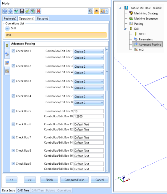
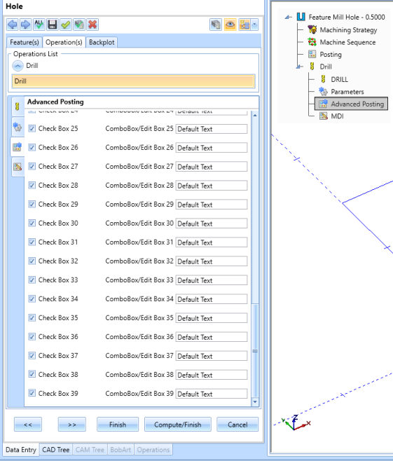
Advanced Posting Page - Support for Unlimited Number of Check Boxes, Edit Boxes, and Combo Boxes
Thanks to the new CAM Wizard, you can now have any number of Check/Edit/Combo Boxes on the Advanced Posting page! There is no longer a limit since the new dialog allows you to scroll down if the number of boxes exceeds the size of the window.
Further Support for Helix Moves - Number of Revolutions and Helical Direction G-Code
In the previous version of BobCAD-CAM, we added new Post Blocks to handle Helix Moves. In the new version, we have added further support for helix moves with the new post variable, helix_num_revolutions, which sets the number of revolutions in the helix move line in the g-code. We also added Post Questions: 735, 736, and 737. 735 handles the prefix for the new helix_num_revolutions post variable. 736 sets the Helix that moves in the clockwise direction. 737 sets the Helix that moves in the counter-clockwise direction. Both 736 and 737 are called from the g_arc_move post variable. Make sure this post variable is in the Helix Blocks (67, 68, 69) if you need this type of output. If the helix segment were to make 1 complete 360 degree revolution and the prefix on 735 is set to "D", the output code would be D1.
New Post Questions Added:
735. Prefix for Helix Num of Revolutions (helix_num_revolutions)? "D" : Prefix for helix_num_revolutions
736. G Code for Helix CW? "G06" : used with g_arc_move
737. G Code for Helix CCW? "G07" : used with g_arc_move
New Post Variable added:
helix_num_revolutions : Number of revolutions in the helix segment being posted out. If the helix segment makes one complete 360 degrees revolution, the helix_num_revolutions will output D1. With “D” being the prefix setup in post question 735.
Example of how to implement into post processor:
Add Post Blocks
67. Helix move XY
n,g_arc_plane,g_arc_move,x_f,y_f,z_f,arc_center,feed_rate,helix_pitch,helix_num_revolutions
68. Helix move YZ
n,g_arc_plane,g_arc_move,x_f,y_f,z_f,arc_center,feed_rate,helix_pitch,helix_num_revolutions
69. Helix Move XZ
n,g_arc_plane,g_arc_move,x_f,y_f,z_f,arc_center,feed_rate,helix_pitch,helix_num_revolutionsAND...
733. Prefix for Helix Total Angle? ""
734. Prefix for Helix Pitch? "K"
735. Prefix for Helix Num of Revolutions (helix_num_revolutions)? "D"
736. G Code for Helix CW? "G06"
737. G Code for Helix CCW? "G07"
Example output code: Spiral Entry from a Mill 2-Axis Pocket
N08 G07 Z0.0588 I0.1111 J-0.0572 F3.3369 K0.0412 D1.
N09 Z0.0177 I0.1111 J-0.0572 K0.0412 D1.
N10 Z-0.0235 I0.1111 J-0.0572 K0.0412 D1.
N11 Z-0.0646 I0.1111 J-0.0572 K0.0412 D1.
N12 Z-0.1058 I0.1111 J-0.0572 K0.0412 D1.
N13 Z-0.147 I0.1111 J-0.0572 K0.0412 D1.
N14 Z-0.1881 I0.1111 J-0.0572 K0.0412 D1.
N15 Z-0.2293 I0.1111 J-0.0572 K0.0412 D1.
N16 Z-0.2704 I0.1111 J-0.0572 K0.0412 D1.
N17 Z-0.3116 I0.1111 J-0.0572 K0.0412 D1.
N18 Z-0.3528 I0.1111 J-0.0572 K0.0412 D1.
N19 Z-0.3939 I0.1111 J-0.0572 K0.0412 D1.
N20 Z-0.4351 I0.1111 J-0.0572 K0.0412 D1.
N21 Z-0.4763 I0.1111 J-0.0572 K0.0412 D1.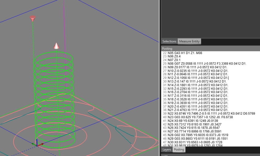
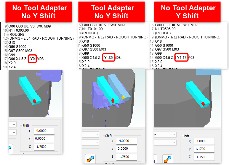
Adding a Y-Shift in the g-code when using Lathe Dual Tool Holders
3560. Output Lathe Tool Y-Shift in the g-code? yThis is needed for some Millturn machines.
This post question controls the Lathe Tool Y-Shift g-code output. This question is needed on some machines when utilizing a lathe dual tool holder. Since the Lathe tools are not centered on the mounting point of the station, the g-code needs to reflect that shift in Y. This Y-shift value can be controlled 2 different ways.
1st Way: If this post question is enabled, if you have a tool adapter setup in the tool crib, it will automatically post out the Y-Shift based on the position of the lathe tool in the tool holder and the center point of the station.
2nd Way: If this post question is enabled and you do not have a tool adapter setup. You can use the Y "Shift" section of the tool crib to manually input the Y-Shift.
Adding Default Values for Custom MDI Commands
You can now add (var) at the end of the following post variables to set default values for your custom MDI commands: mdi_custom_double_xxx(double var), mdi_custom_int_xxx(int var), and mdi_string_double_xxx(string var). If you do not want to set a default value, simply keep the (var) off and it will continue to default the values to 0.
Before:
Example Post Block Line:
2600. Custom Y Value
    "Y",mdi_custom_double_YAxis
Output g-code if user sets up 2.5 as the value in the MDI dialog:
Y2.5
"Y" - A hard-coded prefix
mdi_custom_double_ - the variable to output a user-defined decimal value (Must be exact syntax)
YAxis - the name you give the variable.
After
Example Post Block Line:
2600. Custom Y Value
    "Y",mdi_custom_double_YAxis(3.123)
Output g-code if user does not change the default value in the MDI dialog:
Y3.123
Used in the MDI Post Blocks: 2600 - 2699
Optimization of the "Auto / Y Axis Mode" Posting Mode
If you have “Auto / Y Axis Mode” on the Posting Page for a Millturn job selected, there is now a check in place. If the Y axis runs into a machine limit, when you post the code, it will use Longhand Code (XC Moves) in the posted code and not throw an error. This means you do not have to go back into the settings and manually adjust the Posting Mode anymore IF the Y travel is being reached!
Note: Just keep “Auto / Y Axis Mode” selected in the CAM Wizard UI. This is intended, as the word “Auto” for this mode suggests that there is some logic built into the mode to where it will choose which mode works best.
New BobCAD Lua APIs
Note: Make sure to check the BobCAD Lua API Help System for a list of all information involving Lua APIs for the BobCAD-CAM Product line: BobCAD Lua API Help System
Encrypt Post Processor Through A Lua Plugin
It is now possible to encrypt a post processor inside of a lua plugin using the Bcc.EncryptBcPstFile Lua API function.
Syntax:
Bcc.EncryptBcPstFile(org_post_file_location, encrypted_post_file_location, {customer_id = {ids}, license_id = {ids})
-- Example:
-- Create an encrypted BC_3x_Mill.BCPst for use with customer IDs 1234, 4321 and license IDs 35912217,5678, 8765.
-- Then, place the encrypted post processor in a specific folder location and choose a name (eg. BC_3x_Mill_Encrypt.BCPst)

local ret = Bcc.EncryptBcPstFile(
    "C:\\BobCAD-CAM Data\\BobCAD-CAM V38\\Posts\\Mill\\BC_3x_Mill.BCPst",
    "C:\\BobCAD-CAM Data\\BobCAD-CAM V38\\Posts\\Encrypt\\BC_3x_Mill_Encrypt.BCPst",
    {customer_id = {1234, 4321}, license_id = {35912217,5678, 8765}}
)
For more information about this API, see full documentation HERE